Jim,
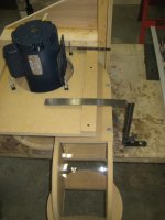
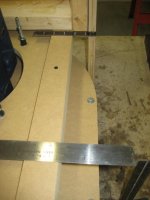
I had always planned to mount the unit on the back wall of my equipment closet. As a 6" exterior wall with brick veneer, it should be pretty immune to vibration. Please see the attached pdf fiiles of my shop layout and the equipment closet. In laying it out, a problem became quite apparent. I had not previously realized that the impeller housing is asymmetric. I have a left hand unit so for the exhaust to come out on the right side, the outlet is in the rear. The problem is that the impeller housing plus the width of the transition flange project well over 4" behind the back of the motor mount bracket support plate. I have attached a couple of photos where I assembled the components on a table that hopefully illustrate this.
Would it help to loosen the main plate and spin it 90 degrees on the motor mounting? If I remember right, the holes for those mounting bolts are symetrical. Or is this what you did to mount it on the other wall as stated below? Or am I missing something else? That's possible, because I'm a very visually oriented thinker.
I woke up very early Saturday morning from a dream about a different CV mounting location. Instead of mounting the unit on the back wall, how about mounting on the side wall? I immediately got up and laid it out in AutoCAD resulting in the pdf files attached. In this configuration, the inlet will come in from the rear of the unit and the exhaust will come out the front, both near the back wall. This allows good access to the dust bin and also allows a straight on approach in mounting the motor in this shallow closet. Do you see any problems with this mounting location?
No, looks like that will work fine in this set up.
There are a few issues I see with this, perhaps the biggest is how to fasten the inlet to the cyclone as the attachment screws will be blocked by the cyclone body, especially the back screws. The closet is finished with sheetrock and insulated with rock wool and I want to make as small a hole in the wall as possible for the inlet to go through. How air-tight does the inlet connection need to be? I might be able to wrap it with duct tape, but I don't think I will be able to reach all of the screws.
This may be too elementary for your background, but may help someone else that reads this later. Mount the rectangle to round transition before you mount the cyclone body to the blower housing. That way all the screws can be put on while it's easy to get to. I didn't use screws on any of the round pipe fittints(That is if the body still mounts to a MDF ring with 3 screws like mine does. I mounted the motor and blower first, then mounted the cyclone body to it.) Mark where the hole in the sheetrock is going to go. Note the angle the pipe will go through the wall, take the cyclone body down and drill a center hole through both sides of the wall with a long drill bit at the angle noted for the pipe. (I have a 1/8" 10" long bit I use for this type of thing.) Cut the holes out, remount the cyclone body and then slide the pipe from outside the closet through the hole into the transition. The hole is not going to be perfect, and you really don't need it to be. After I cut the holes on mine, took a few tries to get the pipe angle right, I took some pipe insulation foam and put it on around the hole, then put the pipe in. It filled the gap, and isolated the pipe from the wall at the same time. If you are worried about the seal, some clear silicone can be added after you put the joints together. You don't want silicone down in the joint or you'll never be able to get it back apart!!! If the silicone is only on the outside of the joint you can cut it with a razor blade and pull the joint back apart if need be.
One thing I can't emphasize enough. Wire the pigtail to the motor before you mount it on the bracket!!!! I failed to do that and it was a pain in the backside wiring it in a closet 10' in the air. You don't have to have the pigtail wired into power at this point, just make sure it is wired to the motor. I'll pm you some other information I found when I put my cyclone in. It may help, may not.
I will need to re-design the duct layout. The single line version shown on the attached pdf files are just my first shot which was done some time ago. I do want to try to get 5' of straight section at the inlet as Bill Pentz recommends.
If the cyclone location is not set in stone, ie: closet already built, I have a great suggestion for you that will simplify you ducting and reduce the resistance in the piping.
When I ran the 10/2 to the equipment closet, I had a 50' roll and just barely made it to the closet from the breaker panel. As a result, I terminated the run in a junction box in the side wall of the closet about 7 1/2' above the floor. My ceiling height is almost 10'4" so I have plenty of height. With this layout, I will be running the main supply through the bracket mounting plate to a service disconnect. I will probably mount all of the CV electrical boxes somewhere on the back wall, roughly opposite from the door.
Sounds good to me.
I'm sure there will be more questions to come and as always, thanks a lot for your comments and suggestions.
Kim Kasdorf (Fingerpicker)