Full Wiring Diagram for Dust Collection System

Chris Peisher

New member
Hello everyone. This is my first post here so thanks in advance for welcoming me to the community of cyclone owners. I purchased my cyclone setup from Ed, in person on New Years Day this last weekend. A big thanks to Ed for meeting me at 8 PM :) I got a tour of the cyclone shop and his personal shop, got to see and hear his cyclone run and i was very impressed with how quiet he managed to get it. I hope i can enclose mine at some point to muffle the noise as well as he did...Any who, i digress...

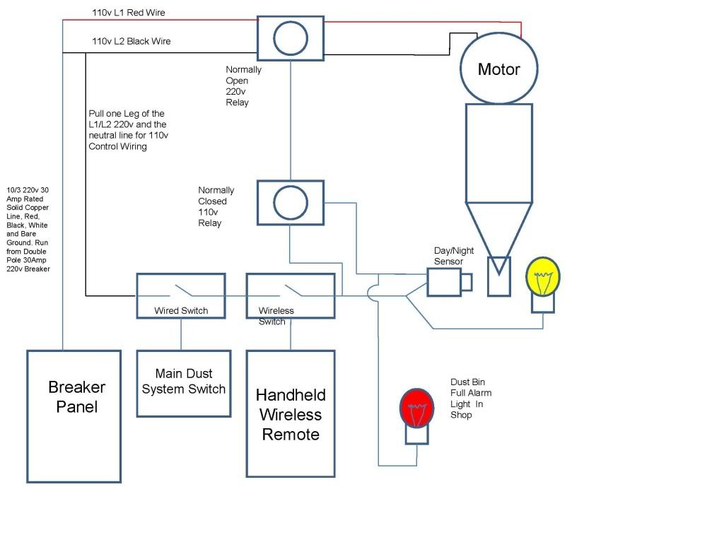
I have read alot of information recently about wiring the cyclones and the big mess people get into when they inadvertently forget to empty the dust bin and they fill their filter stack with shavings, dust, chips , etc. I want to do everything i can to avoid that entirely. I have included a picture of a wiring diagram i developed that accomplishes the goals below. I am not an electrician, but a mechanical engineer. I am submitting this here before i wire it so that i can get some good critical peer review before i attempt to wire all of this myself. Here is what i wanted this wiring scheme to accomplish...

1 - Have a master switch that would disable everything when i leave the shop.

2 - Have a remote switch that i carry on my tool belt to activate the DC from where ever i am in the shop.

3 - Have a dust bin full sensor that gives me a visual warning when the dust bin is full. I wear double hearing protection, ear plugs and over the ear protection as well. Addittionally, I sometimes work late at night in the garage, and i don't want an alarm to wake the kids who sleep one wall over.

4 - Have the same dust bin full sensor turn off the motor to prevent any chips, dust, or shavings from getting to the filter stack.


Please comment and let me know if you see any issues with what i have planned.

Thanks,
Chris

P.S. - The registration page cut the last letter, r, off my last name when i registered, can i get it added or can i change my user name to something else?


Wiring Diagram
DustCollectorWiringDiagram.jpg


Wiring Diagram
 

Attachments

  • Dust Collector Wiring.jpg
    Dust Collector Wiring.jpg
    26.2 KB · Views: 0
Last edited:
Chris -- Looks like you've incorporated some good thoughts into your cyclone installation to safeguard operation. I put together a bin full sensor circuit about two years ago and then upgraded it to add a shop strobe lamp and a bypass switch last year in another thread. The 7 watt incandescent bulb has been replaced with an LED candelabra bulb to reduce the potential for overheating and to add longer bulb life. I also added some details to the original thread from February of 2008 to show the newer circuit and sources for key parts (see #12 and #13).

Hope this helps confirm your thoughts.
 
Last edited:
Hi Chris,

I found it best to have a friend who is an electrician to help me (I'm not wired that way:p). I told him what I wanted which is essentially what you have laid out and it was done before I knew it. If you know someone who has a spare Saturday I would say go for it! Something didn't work right, pulled a couple of wires, moved one here and there and just like that it worked. This would have taken me hours compared to his minutes. But this is mostly cause I'm not geared to really understand electricity. The most I can do is wire in a breaker!

Anyway, someone on here mentioned they used a 'bindicator' for their full bin sensor and that they got it for free so don't bother with it... I checked out Ebay and got the tuning fork style for $11! (They typically go for $300-$500 brand new so only get one if you can find a good deal on a used one or if you have that much cash burning a whole in your jeans) Mostly cause the guy selling it a: didn't know what it was and b: couldn't tell if it worked or not with no way to test it. For $11 I had no problem taking the chance and man does it work swell! If you can get one I would highly recommend it, plus its pretty cool!

We have it rigged so that once the bindicator senses the full bin, the cyclone automatically shuts down and 3 red strobe lights go off to indicate the full bin. The only thing to remember is I have to physically turn the cyclone off before opening the bin as it will start right back up again. That can make a big mess fast (haven't experienced it yet, ... fingers crossed!)

Haven't got the remote yet as I tried the X-10 stuff and since I have flourescent lights in the shop the darn thing wouldn't work! So just using a regular on/off switch for now until I get a remote kinda like the one McRabbet recommends if memory serves me right. Don't bother with any X-10 stuff if you haven't gotten your parts yet, just too gimmicky I found.

Added bonus to getting an electrician = more time to spend on modding all the tools for 6" ports. This is where I'm at and man it makes you cry the first time cutting into the expensive tools. I'm finding this is taking as long as it did to get the cyclone up and all the ducting in too.

The only other difference I see in your diagram is I believed all we used was bex 10/2 wire. I think 10/3 went along the lines of it wasn't necessary... but remember I'm not an electrician, you most likely know more than I do!

As for not waking your kids at night while they sleep... I think I would hang the cyclone on the opposite wall in the shop:D!

Either way, good luck with you cyclone, you're gonna love it!
 
Last edited:
Some Component Links

Some Component Links

McRabbet
Why didn't you just use a 110v strobe/light for teh dust bin full light? Wouldn't it have saved you from having to use the 24v transformer? I found a 110v strobe here, and they have a location near my house...

http://www.partycity.com/product/holiday+parties/halloween+party+supplies/decorative%2C+novelty+lights/cannon+strobe+flash.do?search=basic&keyword=strobe&sortby=priceAscend&page=1

Also, where did you get your 7 watt LED bulb? i looked at lowes.com and the only thing i see are color changing LED bulbs...here a link to what i got when i searched for LED

http://www.lowes.com/lowes/lkn?acti...7294&Ntt=led+bulb&Ntk=i_products&N=4294961544

I like the idea of having a low heat, long lasting bulb in there, but i dont want to spend $60 for it...

Crafted,
I thought a bit about the problem of the DC turning back on when you remove the lid and the light shines through again. It could be solved by addind a limit switch to the can lid and relay to the circuit to disconnect the 110v to the 220v relay. However, i really dont want to fool around with mounting a bunch of hardware to the lid of the can and the running a wire from it to the junction box for the other components. What have other people done to fix that problem?

I did include a couple of links below for some of the components im planning on using.

here is the link to the relay socket
http://www.mouser.com/Search/ProductDetail.aspx?R=70-459-1virtualkey52830000virtualkey528-459

and the relay im planning on using

http://www.mouser.com/Search/Produc...C-120Avirtualkey52830000virtualkey528-7870-11


Thanks again for all the input, im really enjoying the feedback.
 
Last edited:
Wiring

Wiring

Chris,
To be compliant with NEC we all should use #8 wire for a 5HP motor. Section 430 is quite clear on this. It is possible to get by with #10 wires in conduit (not in Romex) if all components the wire is connected to are rated to at least 75 deg C.
bababrown
 
have others in the forum all wired this with #8 wire? please respond quickly someone, i'm headed to Lowes in 22 mins!!! :)

Seriously, the #10 solid core wire is rated for 30 Amps and the recommended breaker was 30A right? Why do i need wire rated so high?

I have a 2008 NEC book on my desk, can you tell me where to find that specification? Is it under Article 430, for Motors, Motor Circuits, and Controlelrs? I don't ever use this book, it was jsut here on my desk when i read your post, so i don't know what section or table applies in this situation... Thanks again for your help.
 
Wiring

Wiring

Chris,
Yes, it is in section 430. You are to use the table value in section 430 for a 5HP motor (not the nameplate current) and then increase that by 1.25 to select the wire rating. Most use #10 but it does not comply with the NEC requirements.
bababrown
 
Strobe and LED

Strobe and LED

Chris,

I used the 12 Volt strobe from eBay (under $10) because I had ordered it for another sensor circuit. The A-B relay in my original circuit had a pair of NO contacts that could be used for the strobe and so providing the 12V power is not a big deal.

The second sensor circuit designed by another woodworker is a low voltage system using Genie LED Garage Door safety sensors (STB-BL at $32.50 at Lowe's) instead of 120V components. The whole thing runs on a 12V/500 MA wall wart transformer and has a custom circuit board and a power relay inside a 4" x 4" enclosure for about $75. PM me for more info if you want.

The LED bulb came from Walmart for about $5 and fits a candleabra base. These pics are by a colleague on the NCWoodworker.net forum that developed the initial sensor circuit I referred to in my Feb 2008 thread.

IMG_3095.jpg

IMG_30941.jpg

McRabbet
Why didn't you just use a 110v strobe/light for the dust bin full light? Wouldn't it have saved you from having to use the 24v transformer? I found a 110v strobe here, and they have a location near my house...

http://www.partycity.com/product/ho...asic&keyword=strobe&sortby=priceAscend&page=1

Also, where did you get your 7 watt LED bulb? i looked at lowes.com and the only thing i see are color changing LED bulbs...here a link to what i got when i searched for LED

http://www.lowes.com/lowes/lkn?acti...7294&Ntt=led+bulb&Ntk=i_products&N=4294961544

I like the idea of having a low heat, long lasting bulb in there, but i dont want to spend $60 for it...

Thanks again for all the input, im really enjoying the feedback.
 
Back
Top