I want to measure the performance of my DC, and it is already installed and ducted throughout my shop. I will admit to having a graduate degree in engineering (although not HVAC or fluid mechanics) and yet having a really hard time wrapping my brain around Bill Pentz discussion of the subject. I just do not find it lucid. So......, can anybody point me to a more lucid "recipe" for measuring DC performance.
You are using an out of date browser. It may not display this or other websites correctly.
You should upgrade or use an alternative browser.
You should upgrade or use an alternative browser.
Measuring DC performance - looking for a lucid discussion
- Thread starter wavery
- Start date
Wavery,
Here is my method with some photos on my gallery section (Richard L Brown). I bought a Dwyer 1/8" pitot tube number 167-6 and made my own U-tube manometer but you can buy one from Dwyer for $30 or so. Maybe 12 to 18" of H2O range. Also you need the connecting tubing. Then I drilled a 3/16" dia hole in the side of the pipe at least 1.5 pipe diameters (9") in front of the cyclone inlet and with at least 8.5 diameters (51") of straight pipe on the other side of the hole. Then with the cyclone running and with only one gate open at a time I place the pitot tube 3" into the hole so it is at center and aim it so the nose points into the airflow. Then I measure the differential pressure and convert it to velocity using the info that comes with the pitot tube. I also multiply the velocity by 0.9 because the pitot tube is measuring peak velocity rather than the average over the cross sectional area. I repeat this for every gate so I have the airflow for all runs from basically a single test point (I actually used two different measurement locations). You can find some more info on the Dwyer site and there is discussion of the pitot tube on many sites. Hope this helps.
bababrown
wavery,
I am not sure why you seek to measure your dust collector’s performance. If the goal is to accurately determine the volume of air moving into the dust collector at each drop, then bababrown’s method should work. This method, inserting a tube in a moving air stream, relies on the Venturi effect.
An alternative to his method would be to purchase an Anemometer, the device used in weather stations and in the HVAC business to measure air speed. The Anemometer can be placed at the end of a drop and directly measure air speed in feet per minute. The product of the reading and the cross sectional area (in square feet) of the pipe would reveal cubic feet per minute.
If the purpose is to monitor performance on an ongoing basis so that a decline in performance can be detected and hence alert you that it is time to clean the filters, then installing a tube perpendicular to the air stream and monitoring the rise in the column of water over time could also work. This solution is similar to bababrown’s methodology, but is mounted permanently in the impeller to filter transition, which is what I did. The underlying principle is similar to that used by an Aspirator that produces a vacuum in a chemistry lab. I am not sure that this device could be used to calculate the volume of air moving through a particular dust port. It probably is only useful when detecting a change in air velocity.
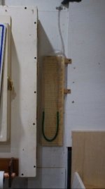
I built mine from StumpyNub’s design. However, I took the time to mark a scale in ¼” increments on the board to which the U shaped colored water-containing clear tubing is mounted. This along with a clean-filter reference mark on the board (when several blast gates are open) allows me to detect a decline in system performance. It was inexpensive to build and easy to install and read. I posted a link to Stumpy's video.
.jpg")
I am not sure why you seek to measure your dust collector’s performance. If the goal is to accurately determine the volume of air moving into the dust collector at each drop, then bababrown’s method should work. This method, inserting a tube in a moving air stream, relies on the Venturi effect.
An alternative to his method would be to purchase an Anemometer, the device used in weather stations and in the HVAC business to measure air speed. The Anemometer can be placed at the end of a drop and directly measure air speed in feet per minute. The product of the reading and the cross sectional area (in square feet) of the pipe would reveal cubic feet per minute.
If the purpose is to monitor performance on an ongoing basis so that a decline in performance can be detected and hence alert you that it is time to clean the filters, then installing a tube perpendicular to the air stream and monitoring the rise in the column of water over time could also work. This solution is similar to bababrown’s methodology, but is mounted permanently in the impeller to filter transition, which is what I did. The underlying principle is similar to that used by an Aspirator that produces a vacuum in a chemistry lab. I am not sure that this device could be used to calculate the volume of air moving through a particular dust port. It probably is only useful when detecting a change in air velocity.
I built mine from StumpyNub’s design. However, I took the time to mark a scale in ¼” increments on the board to which the U shaped colored water-containing clear tubing is mounted. This along with a clean-filter reference mark on the board (when several blast gates are open) allows me to detect a decline in system performance. It was inexpensive to build and easy to install and read. I posted a link to Stumpy's video.
Attachments

Jsbrow,
I question the accuracy of flow measurements at an inlet because of vena contracta. I assume the anemometer measures the correct value of airspeed at the center of the inlet but the effective cross sectional area is in question. The reduction in effective area is dependent on how the pipe is terminated. The actual airflow can be overestimated because of the area reduction.
bababrown
wavery and bababrown,
Since wavery is hoping for a lucid discussion on measuring cyclone performance, I thought I would reply to bababrown and add some words. Whether I am lucid; well I will leave that for wavery and bababrown to decide. While I had some knowledge of physics and chemistry, most of it has been lost to time. To be clear, I am by no means a fluid dynamics expert, although I really doubt my comments would lead anyone to the conclusion that I am.
I agree that for a given volume of moving air, air speed is determined by the size and probably shape of orifice through which the air flows. The volume of air moved in the pipe beyond the restriction should be the same volume moving through the restriction per unit of time since
Cubic feet/minute = (Feet/minute) X (Cross Sectional Area in square feet).
It is my belief that the volume of air moved per unit of time is an important and perhaps most appropriate measure of a cyclone’s performance. That is not to say that air speed is unimportant. If air speed in a length of pipe drops below 3500 feet per minute in the main trunk line or below 4000 feet per minute in branch lines, debris can settle and eventually clog the pipe.
While bababrown may be correct, I am not sure I understand why the volume per unit time measurement at the end of a branch would theoretically be any different from taking the same measurement at the cyclone inlet, even though air speed could be different. This assumes that the only source of air passing through the cyclone inlet originates from the measured branch.
I think how the measurement of cyclone performance is made should probably be driven by the purpose for making the measurements. For example, if the purpose of the performance measurements is to empirically optimize the cyclone’s performance, then measuring at the cyclone inlet makes sense to me. For example, I would expect that a greater volume of air would move through the cyclone inlet if the branch is short, has few turns, and includes no restrictions. But as the length of the branch increases, turns are added, and/or a reduction in the size of the pipe in the branch occurs, the volume of air moving through the cyclone inlet would likely be reduced. These differential measurements would be readily apparent at the cyclone inlet.
But then it seems to me that avoiding long runs, minimizing turns, and avoiding reductions/restrictions are part of the duct work design plan. As a result, I do see much practical use for measuring cyclone performance for the purpose of empirically optimizing the duct system.
When I think of cyclone performance I seem to focus on the volume of air being sucked into the pipe at the machine. It would seem that the greater the volume of air pulled through a machine port, the greater the quantity of dust and debris captured by the cyclone. Thus taking measurements at the dust port would be informative. But then, measuring performance (volume of moved air) at the cyclone inlet would also work.
Even this measurement has little value, since the goal is to maximize collection at the machine. Respecting general principles of dust collection should produce this maximized collection at the machine without the need for measurements.
I do see a big benefit in measuring cyclone performance over time. As dust is collected, the filters become clogged and result in reduced performance at all machine drops. Monitoring the degradation of system performance over time can be taken as a measure of air flow through the filters and when it is time to clean the filters. Monitoring system performance could avoid cleaning filters too frequently or using the system when its performance could be improved by cleaning the filters.
This form of system performance monitoring measurement could be taken at a drop at the end of a branch, at the cyclone inlet, or at the cyclone outlet, although I would avoid measurements at the end of a single branch. Whenever the performance is measured at the cyclone inlet or outlet, having several branches open at once to maximize air flow could avoid problems of limited air flow through a single branch. Accuracy of these measurements are less important than precision. The filters require cleaning when performance has dropped by some amount from the measurement taken when clean. The magnitude of the performance reduction measure is probably best determined empirically, becuase I cannot think of another way to know when the filters are too clogged to allow the cyclone to do a good job.
jsbrown,
I'll try to explain my problem with airflow measurement at an inlet.
View attachment venacontracta.pdf
At an open inlet like the above, air flows longitudinally into the pipe only at the center of the opening. The airstreams towards the edges have increasing components across the opening and lowered components longitudinally. Around the edges of the opening the flow is only towards the center. Unfortunately if one breaks the area into concentric rings it is the outer rings that contribute mostly to cross sectional area. So using the velocity measured at the center and multiplying by the cross section of the pipe gives an overestimated flow. On the other hand the flow in a straight section of pipe as to the right of the drawing is longitudinal. It is true that the velocity increases from zero at the edges to a peak at the center but the velocity can be averaged over the area by at least two methods. So I believe the pitot tube approach is a more accurate way to measure airflow.
bababrown
All, thanks for the great responses. I should clarify in that wanting to measure my cyclone "performance" I was referring to airflow from my various tools. I do not yet have a manometer or anemometer, but in perusing around other threads I noted that maybe current draw might be a good surrogate for an initial look at efficiency/performance. I also recalled that a couple of years ago I planed a bunch of cedar and overfilled the collector bin, but it never occurred to me until I read more that this might have really messed up the filters with clogging. So this pastweekend I did a bunch of current flow measurements with various gates opened and closed. Then I took apart my filter stack, cleaned the filters as best I could, and re-assembled the stack. Cleaning consisted of vacuuming as much dust as possible from the inside of the filters, followed by blowing compressed air through the filters from the outside of the filters, and then vacuuming the inside again I will re-do the current measurements with the clean filters and see what happens. I will put together a story and hopefully post it within about a week. I think I have settled on a manometer I plan to buy. I would like to get an anemometer but am struggling to find a suitable one at an economical price