Venting outside and ducting - I am brand new to dust collection

Nice solution to removing your saw from it's stand so you can work under it! Today is my day to get my filter stack connected to the cyclone. Later this week I will be re-positioning my machines to where I'll plan to use most of them most of the time - then I can begin running some duct work.

If you're still thinking about what 4" flex hose to get, this Powertec hose is well recommended by a number of people in the Sawmill Creek Forum. I've not used any of it, but I've had it bookmarked in case I need to buy some more sometime. Its very nicely priced at just $26 for 10-feet and $45 for 20-feet.
Powertec 4" Flex hose 10-feet at Amazon.com
Powertec 4" Flex hose 20-feet at Amazon.com
 
Thanks Rushton:

I have bookmarked both. I am just about done with my table saw chute. I'm sure it is going to be a little tricky putting it back together because I have to raise the saw 3/4 inch to clear the new stand height, but it is a little bit of a bonus because my bench was just a titch too high to handle outfeed. I have a little more work to do to complete the thing but I expect it to be done on Thursday at the latest... I'll do the overhead part later.

Now.. .has anyone used the hose fitting from Rockler (4 inch) that is used to join two sections of hose together. A splice fitting. I saw a video by an Australian guy who said you could use something like this.. cut it in half and get two fittings and there would be no force to get the fitting into the hose because that is what it is made for, and his video showed that the middle part fit perfectly into a 4 inch pipe... my concern is the Australian part... he indicated that they have their own sizing there and I don't know how it translates... is their four inch different than both of our four inches, etc.... and if the Rockler part is the same and if it will work with the pipe I use. The shipping is the thing. I don't mind paying for the fitting(s), but the shipping is always the thing. I live within 1.5 hours of a Rockler store. I have not been there since I moved to the forest but it is always a fun trip. I'm just curious if someone has any experience with this fitting.

My hood arrived late yesterday. I'm going to put it in after work. I'm already anticipating having to do some work to integrate it with my dust collection.
 
I've gotten my manometer installed and "calibrated" to monitor the filters. The instructions I've found say to seal the outside of the filters to simulate a completely clogged filter. I used 6 mil plastic sheeting to wrap the filters but had to re-tape it THREE times because the force of the exhaust kept breaking the tape at the seams. On the third try, the tape held just long enough to identify a "steady state" maximum rise in the manometer so I could mark worst case. Picture below following third attempt to keep the plastic sheeting from getting blown off the filters, maximum level marked about 8" above neutral state...

Manometer calibration test on filters - Click image for larger version  Name:	Manometer calibration test for filters.JPG Views:	1 Size:	49.1 KB ID:	13331
 
Good morning Rushton:

Thanks for the picture. Why do you have your filter 'sled' on wheels'?

I don't know what a manometer is. I could look it up with Google but I'm afraid it will send me off another project.

I "finished" my RAS dust collection. I took pictures but I'm working just now in my living room on my smart tv and the pictures are downstairs and I don't know how to upload them (if I even can) from here. I'll do that later. I'm happy so far though I think I'm going to make the fence wider like Mr. Howarth (sic?) though I am going to put T track on top for stops rather than the clamps he used.

I got my hood for my mitre saw and I'm happy with it though it is going to be a little bit of figuring to integrate my dust colllection. I think I know how to do it, but having the hood buys me some time to finish my table saw.

I finished the dust chute and ordered hose and fittings to connect that. I'm not researching the overhead part and I thnk I found the design I want. I had thought today about making a 'clamp' that would secure the hose parallel to the fence using the fence, but then I realized the fence moves, so I had to dismiss that idea... but then.... I found a video of a guy who made a jig that mounted to the fence with an overhead 'boom' that slid on T tracks horizontally and vertically. He bought a hood from Penn State Ind. with 2.5 hose... and that put me off for a moment until I did the math on the difference in area between 2.5 and 4. I am think what Im going to do is make (or buy) a 4 inch to 2.5 inch adapter for this so that I can just use my 4 inch hose. I believe this is going to complete my table saw.

And finally, I am going to start the process of cutting my barrel today. It is going to be something of a process. Something occurred to me as I thought about the circule cutting link you sent me, along with my idea of cutting the barrel on the bottom instead of the top... I much prefer cutting the bottom, but I also thought, after that link, that I could make 2 cuts on the barrel. One close to the bottom rim and another to adjust for height. I could then cut a 'donut' as demonstrated in the video and use it to attach the original bottom to the newly cut barrel. That gives me the metal contact to the floor.

I am also going to cut a view port in the top. I'll make an MDF bezel, but I think instead of wiring lights of any kind to it, I'm going to just wire-tie (or something) a small LED flashlight to the top. I'll have to change batteries here and there but I don't be dealing with any more cords.
 
Hi Ed,

Glad to know that you are finished with your dust collection for now! If you post pictures, I'll be interested to see them. The last you posted were very good to see.

Wheeled Filter 'Sled'. I have the filter 'sled' on wheels because I originally needed to roll it about in the shop (before it got attached to the cyclone) as I was reorganizing and before I had the rest of the cyclone ready for it. When the cyclone was ready for the filters to be attached, I decided to leave the wheels so I can roll it out of the way to access a lumber storage pile behind it.

Manometer. A manometer is very much like a barometer but it measures relative air pressure in your filter stack. They are easy to make as a diy project. When connected at the filter stack, it will show you how much relative back pressure your filters are creating for the exhaust line. This DIY manometer is simply a 3/8ths inch inside diameter vinyl tube filled with water and food coloring. The top end of the tube is open (not visible in my picture) and the bottom end is sealed into the dust capture bin at the bottom of the filter stack. As the filters clog over time, the back pressure becomes greater and greater. You can see this as an increasing amount of fluid rising in the manometer's tube as compared to when the filters were new and completely clean (open). When the fluid level rises more a couple of inches, it's time to clean the filters. Wynn Environmental has DIY instructions on their website and a link to a YouTube video by DIY Tyler.

Here's a close-up shot of my manometer's "gauge" with the cyclone turned off:

Click image for larger version  Name:	Manometer gauge.JPG Views:	2 Size:	43.3 KB ID:	13335

When I turn on the cyclone, the fluid level rises to the "New Clean" mark, about 1/4", With the filters fully sealed in plastic, the fluid level rises to the "Totally Sealed" mark when I turn on the cyclone.

I figured right now was the good time to build and install the manometer because my filters will never be any cleaner than now so I get the best baseline measurement.

Today I'll finish building a pipe cutting jig for my Sawzall and start on the first leg of ductwork over the the RAS.
 

Attachments

  • Manometer gauge.JPG
    Manometer gauge.JPG
    43.3 KB · Views: 0
Good afternoon:

Thanks for the explanation! I don't see me doing that. I see the value in it but I am prioritizing getting things ready for actual work. I have a lot of projects I want to get started.

I went out today and got some material.. need to rehang my air filter and I am going to make that overhead collector for my table saw. I got some magnetic sheets to plug the gaps around my bevel adjustment wheel and some magnets for the MDF pieces that will cover as much as possible of the gaping hole in the back of my table saw where the belt goes through, etc. I tried to find rare earth magnets at Home Depot but they don't sell them, or I was looking for the wrong thing. I also tried to get square head bolts for the slots on my table saw bench. They don't sell them anymore, but I realized when I got home that even hex head cap screws have 2 parallel sides and 1/4 inch bolts fit in my fence t-slots. I just have to order the handles from Rockler. I have a boatload of them but they are all 5/16. When I need T track, I usually just buy the kit. The diffrence in cost between a piece of T track and T track with the bolt kits is not really consequential.

I never did get my barrel cut, but I did see another link that I was not able to paste here... Eagle Lake Woodworking. This is the guy who designed the overhead device I'm going to make and he also made a router lift kit that fits into the open end of his table saw which I believe I'm going to build so that I can reclaim that space AND use the overhead mechanism on the router as well. Wish I had seen it in time to incorporate it into my saw dust chute.

I am really making progress on a clean workshop. This cyclone (and this association with all of the people in this forum) has really moved me to another level. I'm going to be retired in 2.9xxxxxxxxxxxx years. (I track those decimal places in an application I wrote and use for work, but I don't know what they are on the weekends.. just 2.9xxxxx years), and I'm going to be READY!
 
Ed, some thoughts following your last post...

Rare Earth Magnets. Here are two online sources of neodymium magnets that I keep bookmarked because of the recommendations I've received about both of them. I can't personally attest to either one, but I hold on to the bookmarks:
K&J Magnetics
Magcraft

Router Lift at End of Table Saw. Have you looked at Jay Bates' design? He paid a lot of attention to dust collection in building this and his lift mechanism seems brilliantly simple and reliable. I plan to build this into an outfeed table/bench for my RAS. See https://www.youtube.com/watch?v=2WyOskBpz_k
 
Last edited:
egbell,

I have found that closet bolts used to secure a toilet to the flange work well in T stacks. The low profile head has no square corners allowing the bolts to slide easily in the T track. Many offer score lines every so often along the length of the bolts so the bolts can be snapped or easily cut to whatever length works best. It has been so long since I have bought any, I cannot say whether closet bolts are ¼” or 5/16” or some other size.
 
Good morning:

Rushton: Thanks for the tip on magnets. Home Depot had magnets labelled neodymium. I did not realize those were rare earth magnets. I bought a pack of 40 ceramic disk magnets (1/2 inch dia)... of course selecting the one that is not the one I wanted... did not know. I'll try the ones I have. If they don't work I can find something to do with them. I got a package of 3 sheet magnets (suggestion from somewhere on YouTube) and covered up the slot where the height adjustment wheel on my table saw is. Jammed pipe insulation between table and housing on the front. Toying with Great Stuff for the sides where the gap is small. I've had the table saw for many years and have never had occasion to remove the table from the housing. The magnets are for a scribed back cover that will cover up most of the gap around the motor/belt. I'm a little ambivalent. It seems I don't really want to cut off every last bit of air flow...

My saw has developed, as of last night, a severe ringing noise that is VERY intolerable. Not sure what the problem is. I'm going to take the blade off after work and see if the noise goes away. First I've noticed it tho I have not used it much since I reassembled it to the base with the sawdust chute. My hose has not arrived so I have not attached the saw to my dust collector.

I looked at the link you posted for a router lift. It is nice, but a lot of work and I prefer a screw type adjustment to the lever shown. (did you notice this guy has some kind of wooden fixture between his cyclone and his barrel... I want to go back and see if he explains that anywhere.. may be something I want to try). The router lift I'm looking at is here:

http://lumberjocks.com/projects/240074

It is designed for what I want, in my table saw extension, and uses a 90 degree drill adapter to allow winding it from the side of the table. It is pretty spartan.

I did the last glue up stuff for my RAS fence last night. I will assemble it and get a couple pictures. It won't really work for you because you make far more use of your saw than I do of mine. Mine is primarily for dadoes... one saw kerf at a time. No mitres, routing, drilling, shaping, ripping, etc. I'll do the final assembly and get the pictures because everything will be done including the hose between blade guard and the rest of the collection fixture.

Last night I rehung my air cleaner. That went very quickly. More dust removal and this one can be set to run for 1, 2, or 3 hours, so I leave it on when I leave my shop for an hour. Just FYI, I also found I can take my shop vac filter, plop it on the ground a few times to remove most of the dust, then hold it to a cyclone drop to clean it out.. almost as good as new, and I'm thinking I may be able to do the same thing with my air cleaner filter... (and next, if that works, I might try the furnace filters I use)

JSBrow: Thanks for the toilet flange bolt suggestion. I had actually thought about using them but I did not buy them when at the store. It occurred to me that even 1/4 inch cap screws have 2 parallel sides and might work. As it happens, they do, so I just need 1/4 inch knobs. Home Depot did not have those that I could see. I'll check Lowes when I go there again... they are a little farther away. I should check to see if 5/16 cap screws will fit because I have a lot of knobs, but they are all 5/16 inch. I did not get started on my overhead fixture because I had other things to get done. I did buy some oak for the link to my fence, so I have enough for a good start which I will do either after work today or tomorrow. I'm going to buy a blade guard/collector from Penn State Ind. that has 4 inch port. Factor aggravation and I cannot make it for their price (about $30).

I have been wondering if anyone has ever made a spring expander... like a muffler pipe expander... to expand flex hose end just a little to fit more easily over pipe. I have not done much, but I have some to do and I know my knuckles are in for a beating. I *did* figure out how to remove the wire, as you suggested earlier. I had to cut the spring wire into sections, but once I got the hang of it it got a bit easier. I tried gluing that sewer pipe but the glue did not seem to work. It was an experiment... I cut a kerf through a short section of pipe and tried to glue the pipe together losing the 1/8 inch section. Just would not take. Perhaps I used the wrong glue.. I used PVC glue and maybe I should have used the multi-purpose stuff.
 
Ed, sounds like progress is being made, step-by-step. I like your solution to filter cleaning!

Knobs. I just can't bring myself to buy the ready-made knobs. Wooden knobs just feel so much better in my hands, and when they take only 20 minutes or so to make, I can't resist making them as needed. Here are two I cobbled together to hold a retaining block for my dust bin lid. But I can understand the need to allocate one's time to more important tasks.

Knobs.JPG
 
Good afternoon:

Rushton: Do you also have a CNC machine or did you do those with a drill? I have come to use a lot of T track and I just get the knobs in a set with that, but I don't think I would get such consistent results as you got there.

I was tooling around the Internet today looking at router lift projects and had my humility restored as I looked at the work being done. This really does help me keep myself in proper perspective.

My four inch hose and clamps, etc. are due tomorrow, so I can get my table saw connected, but it has started making a horrible ringing sound when it runs. I have to figure that out. It is drowning out the cyclone even with my ear protection. I'm going to start on the overhead part of the dust collection for that tomorrow after work as I have some other things to do after I post this.​​​​
 
I make the knobs with a drill - 1/2" Forstner bit in a drill press, then band saw, then a spindle sanding drum in my drill press. I generally follow the process Earl Davidson describes in his video for making six-lobed knobs, adapting as needed. I typically use tee-nuts rather than threaded inserts and use plywood scraps. If I need to make the tee-nut captive, I'll add a stand-off like the ones in my picture using a hole saw to cut out the stand-off blank.

Right now I've gotten diverted to building a movable stand for my floor-standing drill press. I figured since I had to move it to get it in position for the dust collection system, I might as well build the base for it that I've been threatening for so many months.
 
Last edited:
Good morning:

I would be very interested in any plans you have for a drill press bench. I recently made a table with extendable wings for my drill press. It is on a bench with a small belt/disk scander, and now the table overhands the sander and makes it all but unusable. As part of this dust collection project, I plan on making just such a bench, which must be mobile, and I have not really taken time to do research on a bench for that. It is a bench drill press and I know I need to make something that will not be susceptible to tipping because of the nature of a drill press. Your design may be what I need. The bench on which mine now sits is the only one in my shop (carrying a tool) that is not mobile, so please, if/when you find a design, share it. I mainly need overall dimensions, if plans are not available or cannot be shared. The drill press and the sander are both in my plans for dust collection and the new bench is required.

I looked at the link for the knobs. I learned something there... about the threaded inserts.. that they should be installed slot facing into the hole. I have some of these... also came with my set of knobs and bolts for t slots... I used them, ironically, on my drill press table. This tip would have helped then. I don't think I'll be making any of these knobs, but it is useful to have the link. I saw a video somewhere else of these being cut on a CNC machine from MDF.

Currently, everything I'm doing in my shop or for my shop revolves around integration with my dust collection system.
 
Since my drill press is floor standing, I'm only making a platform to which I'll bolt the base of the drill press. The platform will engage wheels when tilted back. This way it can be mobile when needed, but solidly stationary when in use. No storage, no work surfaces. It will sit on three adjustable feet because my floor is very uneven and slopes; I'll send a photo when I am far enough along that you could see what I'm doing. If I later add a storage cabinet, it will fit over top of this base but be independent of it.

Evening Update: 3-points of support did not work. Simply not sufficiently stable for my comfort even though I've seen others use 3-points. Back to the drawing board. Thinking now of doing a torsion box base to keep it thinner (less tall, while still very strong and rigid) and use 4-points of support for better stability. One success were the rear casters positioned 1/8th" high (off the floor) and then engaged with the floor when the front was raised an inch or so. That portion of the design concept is a keeper.
 
Last edited:
Good morning:

After I read your post about your drill press, I went out and did a search on drill press carts. All I wanted was a stable set of dimensions, which I now have, but I also saw quite a few stationary designs for both bases and cabinets to wrap the column. My concern for my bench top is similar to yours for stability. I'm sure you'll find one you are comfortable with. I don't want to deal with something that tips because a rolling wheel encountered a power cord, etc. and drill presses are heavy in either variety.

I had a couple of thoughts last night about my dust system.

First, on the basis of one of the links you (Rushton) sent me, I am toying with the idea of some kind of box transition between my cyclone and my barrel. My thinking is that it will have a piece of 6 inch pipe at center enclosed in a wood or MDF box. The box and pipe would be split so that, with some threaded knobs, it could be easily separated and removed totally from the barrel. No flex but that would not be an issue and neither should the barrel height. I think it will eliminate the need to cut the barrel at all. I could make a clear window on two sides of the box/pipe to allow for eventual bin sensor use and would not have to worry about translucent or opaque hose.

The other idea was my table saw. My hose came yesterday and I hooked up the new chute to my cyclone. It was cool... to the point where I had to stop sample cutting and consider the eventuality of seeing one or more thumbs spinning in the cyclone along with saw dust as I turned to watch it work.

I turned my attention again to the table saw overhead collection. My blade guard has not been used for years, but I put it on last night and it is thin, but sufficiently large that I can cut a slot in the top that would accommodate a 4 inch hose fitting, which I am going to enclose in an MDF chimney. I was going to have to buy a blade guard anyway, and since I'm not using the one I have, this is a win-win. If I mess up the plastic, I can just remake it with one of many designs I've seen in videos, and mine includes the riving knife so I have a good foundation no matter what I do. I am thinking this is going to be a lot less work than I originally envisioned, and that will be one more tool integrated... another of the big hitters. Next is the miter saw (something under the hood), and after that the planer, then the router.
 
It was cool... to the point where I had to stop sample cutting and consider the eventuality of seeing one or more thumbs spinning in the cyclone along with saw dust as I turned to watch it work.

The image this evokes made me shudder... Glad you are being prudent and taking precautions. 4" coming off the blade guard should be very effective! Good luck with your surgery on the guard.
 
Good morning:

I was tooling around the Internet and found a link that is ClearVue related and the guy did something I would have dismissed with 6 inch hose to pipe connections. This is the ultimate easy, though I have questions about how effective it is.. perhaps with enough caulk... but essentially, instead of going over 6 inch PVC pipe, he caulked up the inside of a union and stuck the hose into that. It seems like a good idea because, even if it leaked it would be somewhat minimal, at a limited number of locations (2 max?), does not require clamping, etc. I wondered also if it could not be taped as well, and caulked at the joint (before taping). The bonus is that it creates a quick connect fitting. That is essentially what I have on my RAS, but I had to fight the hose onto a small piece of PVC. This would have been SO much easier. I'm not at home just now but I'm going to give this a shot when I get home.

I copied the link to the clipboard but when I opened the forum here, it was no longer available and the site window closed. However, I think you can visualize this. Unless there is a compelling reason this should not be done, I think it is a good solution that does not require heat or snipping spring steel.
 
egbell,

I tackled the problem of marrying of the 6” flex hose to SDR-35 PVC by shrinking the PVC pipe. Several attempts were made until one that prevented unwanted deformation of the pipe was found.

My approach was to double up ¾” MDF (glued and screwed together) and to cut a 6” hole in the double thickness of MDF. I used a hole-saw in a hand held drill. The resulting disk cut from the MDF was saved. Then the MDF was cut so as to bisect the hole creating a two part die. As I recall, I sanded smooth the inner surfaces of the two part die and the outer surface of the disk. The left over disk was screwed to a 3/4'” backer board. The PVC was heated with a heat gun until soft. The softened end of the PVC was placed over the disk secured to the backer board and the die (the two halves of MDF) captured the pipe and were squeezed together using clamps to draw the two halves together with a second set to keep the two MDF halves flat on a backer board. After the pipe was cooled, it was removed from the apparatus. All surfaces that made contact with the PVC were waxed with furniture paste wax to make release from the cooled pipe easier. The 6” flex hose could then be slipped over the shrunken end of the PVC.

What I do not remember is whether I doubled up the MDF and then cut the hole or whether two separate holes were cut and then doubled up. It depends on the depth capacity of the hole-saw.

It did take some time to make the dies and the apparatus is not especially easy to use, but the results were good.

Here are a couple of pics of the set up…
PVC Flex Hose Stamp In Use (600x337).jpgPVC Flex Hose Stamp.JPG
 
Thanks Jsbrow:

That looks a little like what the guy did who expanded the end to a bell-end... you tube video.

I tried something yesterday that I'm thinking on. I cut 1/2 inch or so sections out of the wire on opposite ends of the hose. I did this for like 3 rings. Then I pushed the hose into a 45 degree elbow and taped it inside and out. I don't know if it is going to work, but I suspect it is because this is the last couple feet of the run and there will be far more air moving through the intake of the pipe to allow any to escape between the pipe and the tape. In other words, minimal to no pressure on the joint between pipe and hose, at least as I imagine things. Even better, the hose makes very tight contact with the fitting. This also gives me a quick connect, if I decide to go this route. I like your solution too and may just go that route in the end.

I tried using a hose clamp and heading the pipe.. that did not really work well though I might try that again with a better band. I wonder if one of those actual band clamps could be used if the band part could be protected from the heat somehow... and if they could be clamped that small.. I don't have one so I don't know.

I had another "brilliant" idea that came to me while laying in bed the other night. It occurred to me that I might be able to cut a very thin piece of PVC from the end of a pipe, which I was able to do with a straight-cut snip. My idea was that I could glue this into a fitting simulating a thread at the start of the pipe. Where it went south was that the pVC glue did not hold. I have considered epoxy, but I'm not sure it would work either. Getting that hose into the fitting was difficult enough with sections snipped out of the wire, but it did work. I have a feeling I'd never be able to thread hose in there.... and that was not even my first idea. My first idea was to cut a thin spiral piece of pipe and fit it into the grooves of the hose and then just slip that directly into the fitting... I can see now that would probably never have worked... and what got me started on all of that was some guy fretting that he did not want to glue his fittings and he felt that even tape was too permanent so he got corded weather stripping, which looked interesting for pipe fittings but I don't know if it would work with what I considered.

I have a couple questions about what you did.
1) Was there any deformity at the gaps between the two halves of the die? Those gaps are probably a lot smaller than I'm thinking...
2) You have the inner disk labelled Hose ID. Is that actually less than the hose ID? I'm only asking because it seems like it would have to be in order for the hose to fit on the compressed fitting, if I understand things right.​

I had been trying to figure out how to do something like this and it looks like you did. I don't have a 6 inch hole saw, but I could probably do the cuts with my sabre saw or jigsaw and sand it to a line.

I have 4 inch fittings and the 4 inch hose slips on that like a champ. I finished my table saw connection top and bottom in 4 inch (I'll post pictures as soon as I can get them) and am moving to the mitre saw, which will be 6 inch, at least that is my first go at it, and that is how this came up again. The only way I was able to get the hose over the 6 inch pipe before was to do as you suggested earlier and remove some of the wire and then heat it to soften the hose. Also an option but even that is difficult compared to the 4 inch hose and fittings.
 
egbell,

I have not seen the YouTube video to which you referred but it may be similar to the method I used to stretch the inside diameter (ID) of the pipe.

The setup I used to stretch the ID of the PVC pipe began by making a disk (die) whose diameter matched the ID sought. However, I allowed for a “loose fit" by adding 3/8” to the diameter of the stretching disk.

If I recall correctly I used the Milwaukee 6-3/8 in. Recessed Light Hole Saw to cut the three ¾”thick pieces of MDF stretching disks (https://www.homedepot.com/p/Milwauk...{brand}+light+{product}+6"+install+kit+{rest}+). The three disks were then face-glued and screwed together, using the center hole for alignment.

The outer edge of disk (that would contact the pipe) was sanded smooth and edge along one face was chamfered with a rasp. The chamfer made slipping the heated and softened PVC easier over the disk. Two coats of furniture paste wax were applied the edge of the die to make releasing the PVC pipe easier, although I am not sure it helped. I applied fresh wax each time the die was used.

When the pipe cooled, I found removing the die was challenging. The method I used was to strike a 1” x ¾” stick resting on the die with a hammer several times along the inside wall of the pipe to pop the disk out. Also the die was attached to a ¾” plywood backer board. The backer board was large enough so that I could stand on the backer board, making starting the pipe over the die a bit easier; the die remained flat and could not rotate.

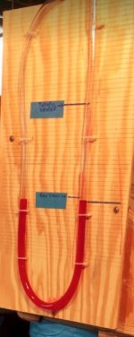
I made a couple of quick disconnects by stretching the ID of one end of a pipe while reducing the OD at the opposite end of the same length of pipe. The end of a short piece of PVC (about 8” long) was stretched so it could slip over unmodified PVC pipe. The opposite end of the short piece of pipe’s OD was reduced to accept 6” flex hose. The flex hose was attached one end of the short pipe and the opposite (stretched) end slipped onto the permanently mounted piping.

1) Was there any deformity at the gaps between the two halves of the die? I did not experience deformity of the pipe where the two halves meet. After sufficient heating with a heat gun, the PVC was soft and pliable but remained rigid enough to prevent deformation.

When I tightened the clamps to bring the two halves together, the clamping pressure was kept equal; one clamp was tightened half a turn then the opposite side clamp was tightened half a turn and so on. Since the pipe can cool quickly, I tried to bring the two halves together as quickly as possible.

I noticed that as the two halves were clamped together and began squeezing the pipe, they would lift. The lifting problem was solved by screwing one half to a ¾” plywood backer. C clamps were used to keep the unattached half down and flat on the backer board. The backer board was elevated off the floor using a pair of 2 x 4 scraps set on edge.

The inner disk was a subsequent modification. Before the modification, the interior of the pipe deformed as the pipe was squeezed to achieve the smaller outside diameter. The inner disk solved this problem. Chamfering was not necessary on the inner disk since it is smaller than the nominal ID of PVC pipe.

2) You have the inner disk labelled Hose ID. Is that actually less than the hose ID? Yes, but irrelevant in my application. The contraption shown in post # 176 was used to reduce the outside diameter of the 6” SRD-35 pipe so that 6” flex hose would slip over the end of the pipe. That is the new (shrunken) outside diameter of the PVC pipe was such that the flex hose fit over the outside of the pipe. This allowed a hose clamp to be used to keep the flex hose affixed to the outside of the PVC pipe.

This method does produce a lip at the flex- hose – PVC pipe junction where turbulence could affect air flow. One additional step to reduce this turbulence would be to taper the inside edge of the shrunken pipe with a rasp. I do not recall performing this additional step.

The diameter of inner disk was the diameter of the outer two-part ring MINUS 2 times the thickness of the PVC. While I do not specifically recall, I probably further reduced the diameter of the inner disk by 1/8” to ¼”. This further reduction made fitting the flex hose over the pipe a bit easier.

The disk used to shrinking the OD of the pipe was label “ID” to keep from mistakenly using this disk when I wanted to stretch PVC pipe. This is the kind of mistake I could easily make and since it could mean re-heating a pipe, I decided the avoid confusion by adding the label.
 
Back
Top