Wiring: Connecting the Motor

Thanks Bababrown,

That is what I thought it would be but wanted some confirmation. I left the wire cap on the P3, T1 and T1 jumper from the factory and wire-nutted the T1 jumper to the T5. In this way, T1, T5, and P3 are all tied together in the junction box. I am now almost ready to call a strong neighbor to help lift the motor assembly up onto the motor mount.

Kim Kasdorf (Fingerpicker)
 
I'll just add something to make sure of. If you don't have one of the wires, and check through thoroughly, do some investigation before you power it up. I got my motor wired, went to throw the switch and this little nagging voice said to check through the wiring again. I found one of the wire ends sandwiched between the motor and the wire housing. May not of created a problem, but it could have been the completion of a hot wire directly to ground. The wire accidentally got sandwiched there when the factory installed the wire housing and no one caught it. Just an FYI. Jim.
 
Grounding screw

Grounding screw

Afternoon all,

Wiring the motor this PM and noticed there is no 'green screw' inside wiring box. I am assuming all I have to do is add a screw somewhere inside box?

Side note: I received my CV1800 Thursday (6/20/13) and started assembly. Soon noticed that I had received wrong motor mounting plate. Phoned ClearVue and had the correct plate Friday morning!!!! Kudos!!!

Thanks to all!
Robert Parker
 
I don't like the look of the ground going to the box...

I don't like the look of the ground going to the box...

I'm just looking for some advice before I do the very last step...

I ran 8/3 from the panel through the disconnect to the CV electrical box. Black and red stranded hots, white stranded neutral, and (thinner) bare solid ground.

I tied the bare ground to the disconnect's box screw and passed the white through with a wire nut, and expected to do the same in the CV box, but what do I do with the white neutral - there's no apparent place for it?
 
Last edited:
tamathumper,
The white or neutral wire is not used. Just cap it with a wire nut and tuck it away in the box. The power to the motor is 240 Volts AC so there is no need of a neutral as in 120/240 Volts AC.
bababrown
 
You didn't need to run 8/3 (which as you've described has 4 conductors including the bare copper ground). The Red and Black are L1 and L2 hot leads and the White is not used in a straight 240 VAC motor hookup. The Ground wire should be connected to the Green Push block in the CV Electrical Box and a ground wire should continue to the motor junction box and be connect to the metal housing. The neutral wire is only used when a 120 Volt "side circuit" is used off one of the hot legs as with a clothes washer timer or a dryer light.

Please note that I am not a licensed electrician, just have some basic knowledge.
 
Thank you both for your replies.

Just to clarify, so there's no confusion about "ground" or "neutral":

- I've run both hot red and black legs all the way through as L1 and L2.

- I've run the white wire through the disconnect, but then capped it off in the electrical box.

- I've connected the bare wire to the disconnect box, and also to the green grounds in the electrical box.

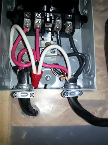
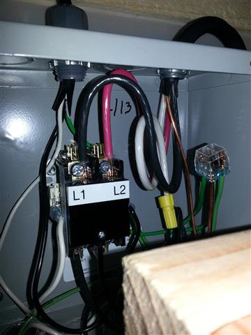
Here's pictures of both boxes for reference. Note that I've tucked the red and black wires behind the screws on the relay, but they don't really fit because they're so big - I'll need some kind of spade connector or something I'm guessing. I've also set the ground wire so it appears to be in a hole in that multi-ground "junction" connector, but it doesn't fit because it's so big, so I'll need to connect it to the electrical box's screw or something similar.

Thanks for your help!

cv_disconnect.jpg


cv_electrical.jpg
 
The wire you chose is actually larger gauge than needed unless you have a lengthy run back to your breaker box -- most of us use #10 wire and just 10/2. With that wire, it is easiest to use a Yellow female quick connector (designed for #10 wire) on the red and black conductors going to L1 and L2 and push them onto the male lugs below the screws. I don't think they will fit on #8 wire. Notwithstanding, your connections at the screws look solid, so you should be good to go. For your ground connections, be certain that you are making good connection to the metal, not painted metal; and continue the ground all the way through to the motor junction box ground screw.
 
Thanks again for your reply. I had opted for the #8 wire because I had read several posts here about it being required for the motor circuit, so I figured it was better to be safe than sorry.

I opted to put washers on the screw terminals for the #8 wire, that provides a "crush" across the entire braided wire and pushes it solidly into the screw and the terminal body itself. It's extremely solid now, and has much better contact.

For the ground, I put two #12's into the ground "push block" and tied them into the bare ground wire with a large wire nut. I was not able to get anything solid or acceptable onto the existing screw, as there's already a wire looped over it, but they're all tied together now.

For the motor body, the ground wire is already connected as part of the pigtail that was provided in the kit, if I'm not mistaken.

I finished everything up, plugged it in one section at a time, throwing the breaker between tests, and finally turned the motor on for about 5 seconds.

Everything was smooth, and there was no magic smoke. :cool:
 
One other thing that many are missing is a disconnect. Going back to at least the 2005 NEC a disconnect is required ahead of the controller (the relay) and the motor. The disconnect must be in sight from the controller, the motor, and the driven machinery. The locks that screw onto the breakers no longer are acceptable. If the service panel is not in view an AC disconnect (50 am) is an inexpensive way to meet the requirement. It adds only about $7.00 or $8..00 th the install.
bababrown

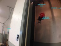
Your second to last sentence regarding the service panel leads me to believe that if the service panel IS in view of the Controller and Motor that a disconnect is not required. Is that correct? Here is my setup, though it requires viewing at a very specific angle, (or in the case of a picture a wide angle lens) you can see the service panel, control box/relay and dust bin sensor box. The 1800 it self is to the right in the same closet as the controls.

DC Electrics.jpg
 
I think it is iffy at best. If you were working on the controller you would not have a clear view of the panel so it is possible you could get a surprise. I think most inspectors would complain. I can't see the cyclone but the panel also might not be in clear view of it. It costs so little to add the disconnect that I would recommend it.
bababrown
 
Thank you for that concern, I'll play it safe. I'm at Hime Depot and pick one up. I think you specified a 60A disconnect. Is that necessary for the single phase 5hp Leeson?
 
Wow. I wonder if my electrician ran a big enough circuit? What the minimums for breakers at the panel and wiring?
 
30 amp breakers are sufficient. AWG 8 copper wire is needed to meet NEC code for a 5 HP motor but most people have used AWG 10 copper wire. Most people specify a 30 amp circuit to their electrician when they should be specifying a circuit for a 240 volt, single phase motor.
bababrown
 
You say that 30 amp breakers are sufficient. Why then is a 60 amp disconnect needed?

What I have found is that I have 10/2 wiring and a double 20A breaker so obviously my electrician did not pay close attention to the equipment I told him I'd be using. I'll swap the breaker out but if you think I can get by with the 10/2 I'll avoid having to cut into my newly installed and painted wall panels. If that wiring is a hazard of course I'll have to do some unwanted work. Reviewing the Clear Vue installation instructions for the 1800 yields the following though…"Our Leeson motor requires a 30 amp breaker." If that is the case would'nt 10/2 and a 30 amp disconnect suffice? I thought it was the amperage that dictated the wire size, all of my 30 amp circuits are run with 10/2, that includes AC and 220 compressor.
 
Last edited:
Stuart,

I believe that Bababrown suggested a 60 Amp disconnect because that is a common size that is available at a home center -- the 60 Amp designation is the switch capacity since there is no breaker or fuse in these devices. Here is a link to a typical one available from Lowe's for less than $15 ( I use a similar one on my unit).

Even though your breaker panel can be seen from your cyclone closet door, it would be better to have a disconnect on the wall adjacent to the final feed to your cyclone (or to the CV Electrical Box if you have one). That way you can be absolutely certain that the power is disconnected before those devices are serviced.
 
Last edited:
Stuart,
I would not change the wire if it is in place. Wiring requirements for motors are different than for branch circuits and the NEC has separate sections for motors and ACs for that reason (articles 430 and 440). It is a shame that the requirements for the cyclone installation have not been updated. A 20 amp breaker is likely to trip since they should not be loaded beyond 16 amps. A 30 amp breaker will not trip under normal conditions with this cyclone. The disconnect must be rated for both current and horsepower. There are two non-fuseable AC disconnects that are readily available at the big box stores. The 30 amp disconnect is rated at 3 HP so it does not meet the requirement. The 60 amp disconnect is rated at 10 HP so it meets the requirement. The 60 amp disconnect costs $6 or$7 so it is no big deal.
bababrown

Stuart,

I believe that Bababrown suggested a 60 Amp disconnect because that is a common size that is available at a home center -- the 60 Amp designation is the switch capacity since there is no breaker or fuse in these devices. Here is a link to a typical one available from Lowe's for less than $15 ( I use a similar one on my unit).

Even though your breaker panel can be seen from your cyclone closet door, it would be better to have a disconnect on the wall adjacent to the final feed to your cyclone (or to the CV Electrical Box if you have one). That way you can be absolutely certain that the power is disconnected before those devices are serviced.

I would like to thank both of you for your patience in sticking with me on this. I have a 60 amp non-fusible disconnect in my possession which I'll install today. The final issue I'd like confirmation on tying each wire into the disconnect.

Here is my plan:

Given that the wire to the CV electrical box has been previously run there is not enough extra wire to run it directly to the disconnect. My plan is to wire nut an additional length of 10/2 to the line and fish the new line a couple feet down the wall to where the disconnect will mount. After it connects to the disconnect it will run back up to the CV box. (Of course all connections will be within the boxes and not loose inside a wall cavity.)

As would be expected the existing feed has three wires, black white and bare copper ground. My set up has black on L1 and white on L2, copper going to the multi connection plastic ground connecter provided in the CV box. The black and white wires will be disconnected from the relay in the CV box and connected to the new wire to their corresponding colors. The copper from the existing feed will stay hooked up as is. The copper on the new wire will attach to a remaining vacant spot on the ground connector.

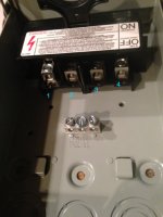
The new disconnect has four main lugs as well as three smaller ground lugs. The ground coming into and exiting the disconnect will mount to the ground lugs.

There seem to be two options for how the line and load wires attach to the four lugs (Now I realize that black and white wires are interchangeable in 220 I will keep them on consistent sides, I'm just that way.) As you see in the picture I have labeled the lugs. Do I wire the line to lugs 1 and 2 and the load to 3 and 4? or Line to 1 and 3 and load to 2 and 4?

Thanks again for your help.
 

Attachments

  • Disconnect lugs.jpg
    Disconnect lugs.jpg
    46.6 KB · Views: 0
Stuart,
Somewhere on the cover or switch you will find two terminals defined as line and the other two defined as load. Connect the feed from your service panel to the line terminals and connect the load terminals to the relay terminals. Also, tape the white wires with black tape to identify them as hot wires.
Bababrown
 
Back
Top