Advice needed on ductwork layout for new shop

Rushton

New member
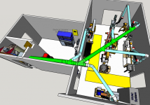
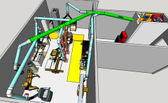
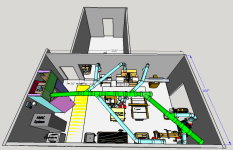
New shop, new dust collection installation... I need your input on the proposed layout for the shop, with emphasis on the dust collection ductwork layout.

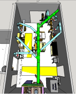
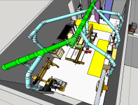
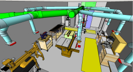
This past year I moved to a retirement community in Huntsville, AL. We're now making serious upgrades to the community wood workshop. My part of the re-design is the dust collection system, which greatly impacts machine locations. I'd appreciate your suggestions on what I've drawn in SketchUp as our proposed layout. Some of you may recall that I installed a Clear Vue CV1800 in my home shop two years ago with great feedback from many of you here.

The dust collector for this multi-user shop will be the Clear Vue CVMAX (5HP, with Wynn Environmental filters) using 8" PVC SDR35 pipe for the main trunk line and 6" PVC thin wall S&D pipe (D-2729) for all the drops. The machines will be mostly Powermatic models. The plan is that we would not have more than two machines in operation at a given time, with only one machine operating at a time (i.e., blast gate open) on any given 6" drop. In this design, I've tried to keep the duct runs as straight as possible, with minimal turns and any 90-degree turns made gradually using 45-degree elbows with some straight pipe in between.

We will install the cyclone and filters in a sound isolation closet, but I have more design work yet to do on that. What you see in the drawings below is just a placeholder design for space planning. I'll make a separate post about the proposed sound insulation closet to ask for your suggestions when I've done some more work on that design.

Our shared use shop is small, about 14' wide by 26' long with 9.5' high ceiling. Fortunately, we have the use of a small side room for additional storage. The yellow rectangles shown on the floors mark 36" wide pathways that we want to keep clear. The pathway marked in front of the cyclone closet cannot have spinning blade tools along it because it is a regular pathway for the community's facilities employees - we want to keep them safe. Because of this "safety zone", it seemed became necessary to locate the cyclone on this wall and let the required 5' of straight pipe leading into the cyclone's intake run over top of this walkway space. (In an earlier draft of the layout, I tried placing the cyclone in a corner so we could run one trunk along the wall with 45-degree drops machines. But we had to abandon that layout when we were told to maintain this safety zone walkway.)

There are no 4" blast gates planned. All blast gates will be on the 6" pipe only to ensure someone doesn't throttle the air flow to the cyclone, not understanding that's what they are doing. (Remember, this is a shared use space and, while we will provide some training/certification to users, we have to plan on varying levels of understanding about the machines.)

Also, I should add that 1) all the machines will be moveable on casters, either locking or retractable. And 2) For the larger volume dust creators, we plan to run solid pipe as close to the machine's dust port(s) as possible. My goal is to have no more than 4' of flex duct connecting the larger machines, but I'm sure we'll end up with greater lengths here and there. And 3) I've not sorted out dust hoods/shrouds, and we will need them for the sanding machines, scroll saw, router table, etc. I will likely experiment with some bell mouth hoods for various pipe ends connections, per the Australian Woodworkers Forum - anyone worked with these?

I welcome and will appreciate your suggestions. Please ask whatever questions you like, as well.
Floorplan A1.PNG

Floorplan A2.PNG

Floorplan A3.PNG

Floorplan A4.PNG
 
Good layout with the exception of the use of pairs of 45 degree fittings instead of a single 90. If you look at page 54 of the "Cookbook" You will see that once you have a 1R 90 degree fitting (25' of equivalent straight duct) you have a losses less than a pair of 45 degree fittings and the straight bit between (15' x 2 + a foot of straight = 31' of straight duct). A larger radius corner would be even better. Verify the radii of the 90 degree fittings applicable to the pipe specs you are buying and decide which way to go from there.

Pete
 
Hi Pete, thanks for the suggestion about using a 1R 90-degree fitting for less resistance than two 45-degree fitting with some straight pipe. Notwithstanding what's in the Cookbook you referenced (and I did go look at it), my understanding of resistance for dust collection piping does not align with this. Until the radius of the elbow gets to 1.5R and, preferably 2R, I've consistently been advised to use two 45-degree elbows. The Cookbook is for HVAC systems and I'm wondering if there may be something different going on with the 3000-4500 FPM air speeds used in dust collection systems.

Perhaps Alan or Rob could weigh in on this. If I can use 1R 90-degree fittings, I'm all ears. But I do not think this is correct for a dust collection system
 
Hmmm... Pete, a quick search of the site brings up an earlier thread in which Rob (McRabbit) addressed this same suggestion you made in 2018 (LINK HERE). He replied to you at that time:

Curly1,

I question the values in the document you cited when applied to dust collection where velocities are much higher in the ductwork as compared to HVAC ducts. According to Bill Pentz' description of 45* elbows versus 90* elbows, he states in his StaticCalc spreadsheet (lines 41 and 42):
Enter the number of pipe 90's. Count 0.5 for each 45 degree bend and 1.0 for each full 90.
R/D is the ratio of the bend's centerline radius divided by the pipe diameter.
I have had very good results using a pair of 45's separated by 18" to 24" of straight S&D pipe. Typical 90* elbows I have found have a short and tight bend, which renders them unusable for dust collection

Have you done any subsequent testing of using a pair of 45s versus a 1R 90-degree elbow?
 
I haven't done any testing. Here in Saskatoon there is no readily available PVC S&D pipe available in 6" or 8" diameter at anything approaching a palatable price ($10 to $16 per foot for 6" and $16 to $25 per foot for 8") so I am not going to play with it to see. I'll happily sit corrected if someone can show me a source, document or calculator that shows otherwise though.

Pete
 
I can understand not buying at those prices just to test. Perhaps someone will comment who has done some comparative testing of airflow impact.

Bababrown on the forum is the only person I've seen report on doing some actual testing. He tested 4" pipe turns in various configurations but he measured pressure drop, not air flow. So I don't know how well his testing actually translates to our needs, which is airflow. In any event, his conclusions were: 1.5R 90-degree is good, 2R is very good, but anything less than 1.5 is not good and you're better off using a pair of 45-degree elbows spaces 5R apart with some straight pipe. I do not believe there is any 1.5R or 2R 2729 or SDR35 elbows manufactured. The long sweep elbows sold by McMaster-Carr and others are, at best, 1.25R and typically only 1R. You can see his data results HERE and some other comments from him about his results HERE.

His conclusion for 6" ducting was to use a pair of 45s because no long sweep 90s are available in the 6" PVC we use for our ducts.

So far, that is my conclusion also.
 
Last edited:
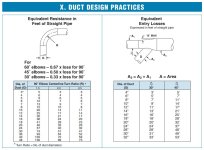
Following up on the discussion of using 90-degree elbows vs pairs of 45-degree elbows, I found a reference to Cincinnati Fan Engineering Data document on duct and transitions design among the Australia Woodworkers Forum threads on dust collection for workshops. (If you're not familiar with this forum, it's a great resource from over many years of contributions.) The Cincinnati Fan data shows resistance loss for various transitions with curvatures of different multiples of the pipe's diameter versus straight pipe.

On page 9 of the downloadable pdf (from the link above), their data for 6" pipe shows a loss of 12 for a 90-degree elbow with a curvature radius of 1.5 pipe diameters (1.5R). This is greater than the radius of standard "sweep" 90-degree elbows available for PVC pipe, which are typically about 1.25R. If you are able to use a 2R long sweep 90, then the loss is only 7, which is about as good as it gets.

But, these long sweep elbows of 2R or greater are not available in D2729 or SRR35 pipe which most of use are using. (If you've found a source, please let me know.) I've only found long sweep 90s it available in Schedule 40 or in metal pipe (e.g., Nordfab).

For 45-degree elbows, their data shows 50% of the loss of the comparable 90. By placing a short length of straight pipe between the elbows (as recommended by many), it seems to me we are approximating a 2R or greater long sweep 90. So, instead of a loss of 12 as we would have in the PVC elbows available from the pipe manufacturers, we can achieve a loss comparable to that of long sweep 90s of 2R or 2.5R depending on the length of straight pipe used to settle the turbulence.

All of this convinces me that we're on the correct path to use pairs of 45s with 6" and 8" pipe runs if we don't have access to 2R long sweep 90s. The tighter radius 1.25R "sweep" 90s found in D2729 and SDR35 pipe (and Nordfab shorter sweep 90s for that matter) is just not a good substitute. Perhaps in the smaller diameter pipe (4" and under) its not as significant a tradeoff given the lower resistance loss to start with.

For quick easy reference, here's an image of their page 9 chart:

Cinncinatti Fan Resistance Loss Chart for Elbows.jpg
Source: Cincinnati Fan Engineering Data pdf, page 9
 
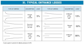
Some additional diagrams found on page 10 of the Cincinnati Fan Engineering Data pdf referenced above are diagrams illustrating the resistance loss for different pipe entrances into our equipment. I often see HVAC take-offs recommended for connecting dust collection pipe/flex into machine cabinets. But, these charts show as much as 50% loss using such a flanged pipe connection!

Instead, we should be using smooth, well rounded connections (best) or a flanged cone connection. So, time to work on creating bell mouth hoods with a 1.5R to 2R radius at the connection points.

Cinncinatti Fan Resistance Loss on Entrances.jpg
 
I agree with the Aussies having the best dust collection information. I have been a member there for a long time (QC Inspector) and Bob, the moderator, is very knowledgeable from his career in the University which included designing clean labs. When you read more you will come across Bob's posts and threads on bellmouth hoods, including how to heat form them from the PVC pipe. The radius of the flare is is 1/4 of the pipe diameter or 1/2 the pipe radius. A 6" pipe will have a 1 1/2" radius flare. You don't hurt anything by going larger but the improvement is almost nil and if forming from PVC it is about the limit it can be stretched before the edge fails. Although not easy to find, the speaker ports used by audio buffs making their own speakers, can be had in 6" diameter with the 1.5"R flare. https://www.parts-express.com/Precis...t-Tube-268-384 Further digging might find other sellers, possibly a bit lower in price.

Pete
 
Yep, with the lathe coming as part of the new shop machinery, I'm planning to make some forms to press PCV bell mouth hoods for various components in the dust collection system. These will all be later enhancements following the initial build of the collection system.
 
Curly1, I think I have finally received some engineering data that supports your recommendation to use a standard sweep 90-degree elbow with our D-2729 and SDR36 6" ducts instead of using paired 45-degree elbows.

In that thread on the Australian Woodworker forum we discussed, beginning with post #24, U.S. member Dmorse discusses the engineering data. Our problem boils down to the curvature of the radius available to us in D-2729/SDR35 elbows. They are all less than 1R.

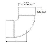
According to Dmorse's post, the sweep 90-degree elbow most commonly available in D-2729/SDR35 pipe is .833R, but the 45-degree elbows are only .5R. The 90s at this radius sweep have a loss coefficient of about .28. But the 45s with their .5R radius have a loss coefficient of about .71/2 each (one-half the loss coefficient of a sharp bend 90). When used in pairs, the total loss coefficient is the full .71 or greater. Much higher than the .28 of the standard sweep 90.

So, his conclusion matches your earlier recommendation (which I'd questioned): of the commercially available choices available to us for D-2729/SDR35 ducts, we're better off using the standard sweep 90s than 45s in pairs. (Contrary to everything I've understood over the years, but the data certainly supports it!)

Sweep 90 - Ninety_75rD_2.jpg

If anyone has some information supporting why we should be using paired 45s, I'm open to hearing it.
 
I saw Dmorse's and Bob's responses to your questions so understand.

Something else that I think affects the airflow but is overlooked or dismissed, is all the extra joints where the pipe is pushed into the fittings. Each bump as the air flows from pipe to fitting or back to pipe again creates a bit of turbulence that adds up in small increments. Much the same as an aircraft wing with round head rivets and lapped seams has more drag and slows an aircraft down compared to one with flush rivets and seams. A duct using a pair of 45 degree fittings has 4 joints to the 90 degree fitting that only has 2.

Pete
 
Makes sense. I've also emailed Clear Vue to ask if they have a recommendation about all of this. Hopefully they will reply.
 
Just in case anyone is following this thread or may come across it when researching, I'm updating this with more information from my conversations with Alan in Little Washington over on the NC Woodworker forum (here):

We found an SDR 35 long sweep 90-degree elbow manufactured by Normandy Products that appears to be built on a bit larger radius than what I've seen from other sources:

index.php


I found the Normandy Products fittings available for retail online sale from Drainage Solutions. Prices are pretty good ($22 for the 6" elbow) and shipping costs seem fairly reasonable.

While this Normandy 90-degree Long Turn elbow is still not what we'd like to have as a long sweep (not nearly as large a radius as available in Schedule 40 or Nordfab), its better than any of the other SDR35 90-degree elbows I've found.

For SDR 35 8" straight pipe and fittings Ferguson Waterworks, locally, has both. They only have the gasketed pipe, unfortunately, not weld bell end pipe. Their sales guy searched for me to see if he could source any weld end pipe, but no luck. Nor did he have access to any D-2729 8" pipe. So, I'm planning to use the SDR 35 for my 8" pipe. Drainage Solutions has the 8" fitting for less than Ferguson shows in their online pricing (e.g., $66 for the 8x8x6 45 wye at Drainage Supply vs. the Ferguson posted list of $113), but Ferguson may match those prices.

I have finally found a local source for 6" D-2729 pipe. It is a landscape supply company called SiteOne Landscape Supply (a U.S. chain with various locations) that Alan pointed me to. You'll have to check if they have a store in your area. However, their retail prices for consumer sales are much higher than their contractor prices. So, if they won't deal with you directly at contractor price you'll want to find a contractor who can purchase it for you.

McMaster-Carr does carry D-2729 6" pipe in 10' sticks and bell end connectors at $32 per stick (current price) (link here) and their shipping cost is not unreasonable. Plus, if I end up ordering some other items from McMaster, they'll try to fit it all on the same pallet to ship.
 
Now that I've found the Normandy Products 6" 90-degree elbows (the ones with the larger radius curvature than others we see), I've completed our duct layout design and thought I'd share it here. I still have some work to finish on the separate 6" drops in the center of the floor for the bandsaw and table saw. In some instances where I've used 90-degree turns for the drops I could have made the connection with a 45-degree drop, but we need the wall space to build in some storage. So, some trade-offs are made in this respect.

Thanks for everyone's help thus far! Questions and comments welcome.

Woodshop floor plan 2-25-2021.png - Click image for larger version  Name:	Woodshop floor plan 2-25-2021.png Views:	0 Size:	515.5 KB ID:	14461

Woodshop floor plan B 2-25-2021.png
 
Last edited:
Hi Rushton,

I am a newly to this forum and I am working on a VERY similar project to yours. I am building a shop that is a little bigger, but has less equipment (s0 far). I too am looking at the CVMax for the added power. The conversation about the long sweep 90's has already been a great help for me.

I have a few questions for you in case you might have thoughts for my system and in case they are new questions for you.

1. I am concerned for my setup and yours about the Static Pressure with the length of pipe and number of corners. In my set up I have calculated the Static Pressure to my longest and most complicated runs using two different methods, Bill Pentz's spreadsheet calculator and my own calculations converting elbows to straight pipe length and adding up the pressure losses. I have literally spent days trying to find more efficient placement for the Cyclone and ducting. No matter how I run my ducting I get about 11.5" of W.C. of static pressure. That is assuming that at the inlet, the CVMax has 4.9" w.c. based on Pentz's spreadsheet calculator. However, I have recently seen something that says the Clear Vue Cyclones actually have about a 2.25" loss at the inlet built in including filters, etc. If that's true, I would max out a 9.1" of W.C. which would feel better.

So, my question to you is two fold:

A.) Have you calculated your static pressure loss with the duct work you are using and what concerns do you have? I have seen a Clear Vue Cyclone Fan Curve that indicates that if we have a static pressure above 10" or 11" of W.C. we will drop below the required 1000 CFM needed on many important machines for fine dust collection.

B.) By my reading, I understand it might be better to have all of your horizontal runs out of 8" ducting and transition to 6" for the drops only. 6" pipe increases the speed of the air to make dust go up, but it creates considerably more static pressure which will decrease the CFM at your machines and limit the fine particulate collection. This is my understanding.... Do you have a different understanding?

2. From your Sketchup drawings, it looks like you have openings in the walls where the ducting passes through. If those are indeed open air passthroughs, it may not be an issue, but if those are more restricted than you show, you might have an air pressure balance issue. i.e sucking air out of the shop with no air returning to the shop. This will cause negative pressure in the shop and limit air flow into the cyclone. (I hope I am not insulting you with this comment, it is something I have had to think about and thought I would pass it on in case you have not considered it.)

I hope to do a similar set up with the collector in an attached garage. For air make-up, I will add ducting to put the filters inside the shop. I am also getting an exhaust manifold that will allow me to exhaust directly outside when the weather permits. (When I do that, I will have to have a window fairly well open. I think 16" x 16" is the free air needed for this much CFM.) I live in a very rural area so exhausting fine dust outside should be okay.

In case you or anyone out there might have an answer to this one. Like you, I plan to use 8" PVC horizontal duct from the Cyclone to 6" drops down to each machine. At my Table Saw, in order to keep the down drop out of the way of things I'm cutting, I plan to go from the down drop to a horizontal under my out-feed table to the base of the table saw. That run is about 9' long. I am assuming I should stick with 6" duct for that horizontal since I have already restricted air flow. However, that 9' of 6" duct accounts for ~.5" of W.C. Which is 5% of my overall loss. I don't know the physics, would it be better to go back to 8" duct for the horizontal along the floor?

I am on a steep learning curve trying to be an engineer when I'm not. I hope someone can help us get it right.

Thanks to anyone who has thoughts on these questions.
 
Hi Rushton,

In my excitement that you are doing a project so similar to mine, I rushed to respond to your post. After spending a little more time on this forum, I see you have been a major contributor to this community for a long time and have a ton of knowledge. Please forgive my not knowing your level of experience.

If you could share your knowledge about my questions above, I would most appreciate it.
 
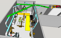
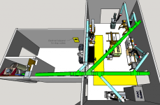
So, for any who have been following along, here is the "final" design of the duct layout for our Clear Vue CVMAX installation - at least until it all changes. I've incorporated several recent suggestions, with great thanks to Alan in Little Washington and to everyone else who has offered comments. I'm moving on to ordering pipe and connectors based on what you see here. Most people will make their layouts using only 6" pipe, just as I did in my last home shop. But in shared use community shop, I have to plan for two machines being operated simultaneously by different users. This design will allow for any two machines NOT sharing a blue 6" branch to be operated simultaneously. This design criteria led to several of the choices of layout for this shop. For example, a bandsaw and the table saw could be used concurrently, or both bandsaws, but not the table saw and the planer.

Summary of changes: 90-degree bends have been eliminated to the wood lathe and to the jointer (per Alan's recommendation). The 8" trunk extension at the first wye has been deleted in favor of an 8-6 reducer to 6" pipe to the sanding station by itself. Two 90 degree elbows still remain in the system since replacing them with paired 45s does not improve resistance over these longer than typical sweep (nearly 1R) 90s. (Too bad we don't have true 2R and greater sweep 90s available in SRD35 connectors.) The branch line into the small work room on the left has been eliminated - all dust creating activities will have to occur in the main shop and we won't mix swarth from the metal lathe with wood dust in any event. Those two salmon colored post are floor to ceiling posts to accommodate bracing for the down drops and to bring 220v conduit down from the ceiling for the table saw and bandsaw.

Blast gates continue to be only at the 6" branch lines with no 4" blast gates. I may need to find a way to reduce some of the 4" lines to 3" when paired with a 6" pipe (that should ideally be reduced to 5"), such as at the miter saw station, but this will be fine-tuning at a later time.

Still to do: 1) more work on the Festool miter saw station layout (which will incorporate below the table dust collection as well as collection through the built in dust port), 2) the movable router table (currently shown in its "docked" location to the left of the miter saw), and 3) improved dust shroud designs for many of the machines, particularly the belt/disc/spindle sanders.

Floorplan 2-27A.PNG

Floorplan 2-27B.PNG
 
One disadvantage of the diagonal pipes along the wall is the loss of space for racks or cabinets for tools or WIP projects etc. I doubt you can make it anymore efficient though.
Enjoy the new shop
Pete
 
Back
Top