Another New CV1800 Installation

SGI Dave

New member
Hello Everyone,

I have completed my CV installation about 3 months ago and am now getting around to getting some pics posted in the gallery (http://www.gallery2.clearvuecyclones.com/v/CV1800+and+CVMax/SGI+Dave/) and a note on the forum.

I am impressed with the performance of the CV. I have numerous bends in my ducting set up due to the layout of my shop space (and probably poor planning on my part). Nonetheless, it does very well. My reference point is my previous DC which was a bare WoodSucker cyclone I bought from Ed Morgano 10+ years ago. At that time I was upgrading from a 2 hp Jet bag-type DC, so I simply mounted the Jet fan/motor on top of the Woodsucker. It worked fairly well. At the time I thought it worked really good, but now that I have a CVC with 5 hp...WOW, it does make a difference to have the higher hp!

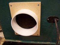
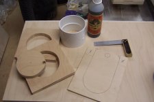
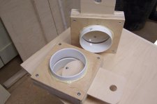
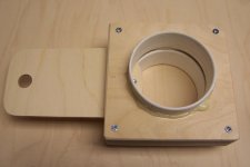
In my previous set up, the cyclone exhausted into a box with 2 filters, mounted end-to-end with OUT to IN filtration. I had a high ceiling (13') in that shop so the cyclone and filter box where mounted high to conserve floor space. Anyway, my faulty design of THAT filter box made it hard to clean the filters. The filters where not removable and cleaning was through access hatches; alas, it was so high-mounted, I needed a 10' step ladder to get to it. Yikes! For my new shop space I wanted the filters at floor level AND in an enclosure which allows easy removal for cleaning. You can see what I came up with in my gallery pics.

The filter box is connected to the CVC via HVAC ducting, flexible 8" with insulation. I gleaned from this forum that the insulated ducting for cyclone exhaust was worthwhile for noise reduction.

I have a sound meter but have not taken it to the shop. I will post db measurements....soon...maybe....

Work Safe!

/david
 
Dave,
looks great.
I am very slowly working on installing my cyclone.

How about a close up picture of your duct brackets and homemade blast gates.

Thanks for sharing
Rob.
 
Hey David,

I like your installation and was pleased to see the picture of the new generation optical sensors that I now supply with the McRabbet Bin Sensor system. In particular, I think the wall mount system you used for mounting them so they do not interfere with emptying the barrel is the best method. I'd like to hear your comments on the system and any issues you may have encountered during installation.

I also like your filter box and would like to see you post more information about its construction.
 
Hey David,

... I think the wall mount system you used for mounting them so they do not interfere with emptying the barrel is the best method. I'd like to hear your comments on the system and any issues you may have encountered during installation.

I also like your filter box and would like to see you post more information about its construction.

Hello Rob,

Well, once again, I got the idea to mount those bin sensors to the wall from reading here on the forum.

Not issues with installation. THus far, I have not wired the CVC power into the bin sensor circuitry. It works as an audible and visual alarm which I think will be fine.

I am nearing a full bin, so when I plane a few more boards, it should alarm. That will be handy as I have never used a bin sensor and really dislike the filter disimpaction process about as much as a root canal.

The alarm did sound once when I was vacuuming a LARGE quantity of dust from my Table Saw cabinet. The hose which normally collects off the bottom of the blade was inadvertently removed so I sucked up several gallons of dust at once which apparently made the overflow sensor think the bin was full. No issues during normal usage.

Thanks,

/david
 
Dave,
looks great.
I am very slowly working on installing my cyclone.

How about a close up picture of your duct brackets and homemade blast gates.

Thanks for sharing
Rob.

Hello rob,

I've added a couple pics of the pipe mounting brackets in my gallery. Basically, I ripped 3/4" plywood 8" wide. Then, depending upon how much 'offset' (or, distance from wall or ceiling) you want your pipe, you cut to length the main piece which will have the 6 1/8" hole. For instance, if you want 3" offset from wall (to accommodate your blast gates, etc), then cut at 10" (3" offset + 6" for pipe + 1" for wood to go around pipe). Trace around a piece of 6" pipe with the edge 1" from the sides and end of the 8" x 10" plywood piece (I'm approximating, the measurement is slightly less than 1" as the pipe is 6 1/8"). Cut a 2" piece off the 8" wide plywood you started with. This will be attached to the end of the 8" x 10" plywood and serve as the place to fasten to the wall or ceiling.

Since there is a 'slit' in the plywood circle, no hole drilling is needed...just cut away with your bandsaw or jigsaw. I tried to cut approx 1/4" out of the circle to allow a screw to really clamp down on the pipe and give good support...important for vertical runs.

Blast gates...I modeled these after some plans I found online. But I cant find them now...drats! Basically, I cut a 6" pipe union in half. I cut 2 pieces of 3/4" plywood and cut a hole for the pipe unions. The unions where screwed into the plywood. I used 1/4" tempered masonite for the slides on the blast gates; 1" strips of this masonite with one strip of masking tape on each side was used as a spacer along 2 sides of the plywood halves. The 2 plywood halves with the screwed on unions where then screwed together. A masonite slide was then cut to fit the resulting slot. My recollection was that the blastgates where approx 10" x 10". I used no glue; only screws. The entire thing was caulked with cheap, paintable caulk, then spray painted white. Simple!

Where I live a union costs $6-7 and the rest is scrap. So, depending upon how you value your time, homemade BGs are MAYBE worth it. It was something I did while waiting for my CVC to arrive!

Sorry for such a rambling description. Hope that helps.

Measure twice, cut once,

/david
 
Shopmade Blast Gates

Shopmade Blast Gates

Hey guys,

I thought I'd show you some that I made using PVC couplings and some scrap 3/4" plywood for the bodies and 1/4" Baltic Birch for the slides. The pictures show the basic method -- I cut the two outer plates first and then drilled a starter hole to enable cutting out the holes with a jigsaw. The slip coupling was cut in half and glued in place with Gorilla glue and the slide cut from 1/4" BB plywood -- the excess is used to leave room for the slide to move freely (I used masking tape to add a little thickness).

As an aside, but also of value to this discussion, I made new ports for my Table saw and a jointer using the same technique -- a 6" hole was cut through the side wall of the cabinet and screwed the plywood plate with coupling over it (see the picture).
 

Attachments

  • 100_4628.jpg
    100_4628.jpg
    66 KB · Views: 0
  • 100_2478.jpg
    100_2478.jpg
    56.4 KB · Views: 0
  • 100_2481.jpg
    100_2481.jpg
    53.3 KB · Views: 0
  • 100_2482.jpg
    100_2482.jpg
    44 KB · Views: 0
Hello Rob,

Your blast gate method is better and more refined than mine. I like your use of BB for the slider piece; the masonite I used is the weak link in the whole affair...especially in the 6" size. I can see where plywood would be more durable.

Where do you get your 1/4" bb?

/david
 
Last edited:
I bought my BB at The Hardwood Store in central NC (Gibsonville, near Greensboro), but you can get 1/8" sheets (24" x 30") that will work very well at Woodcraft for a reasonable price (this is from the Greenville, SC Store). I know some guys use pieces of laminate for their gate slides and many make the slide so it passes all the way through and it has a hole through the slide that aligns with the duct for the open position and just slides a solid section in the way when closed.
 
Just a note: if you want to save the price of the union and having to cut it in half, you can mate the gate to the regular pipe end. That's what I did with mine. I used a router circle jig to get perfectly round holes, and a little trial and error, three tried if I remember right, to get a snug fit on the pipe. Here's a tutorial I did over at SMC on the gates: http://www.sawmillcreek.org/showthr...to-blast-gates&highlight=BUILDING BLAST GATES
and one by someone else...see post 13
http://www.sawmillcreek.org/showthread.php?177313-6-quot-Blast-Gate-for-PVC

Hope this helps someone. Jim.
 
Hello Jim,

THanks for the posts re homemade BGs. The second link has the article pasted into it (post #13)...I like the visual of that sketch. Looking at that again, makes me want to go home and make a few more just for fun....I'd better sit down for a while until that feeling passes;)

I mentioned the masonite being the flimsy part of my BGs...I say that because at one point in the plumbing process, I had several feet of 6" pipe with elbows, BG, etc hanging over my saw and I was adjusting the angles...I momentarily forgot the assembly was NOT screwed together and right after I stopped supporting it...gravity took over and it crashed to the floor. As luck would have it the BG slider was 'open' so that the masonite broke at it's weak point (middle of big 6" hole) but the main body of the BG is fine...it just needs another slider fitted to it.

My previous DC ducting had 6" mains but a lot of 4" runs too, so you can see from my current pics I recycled some of the ducting (I now KNOW that duct tape is NOT the solution for sealing joints...10 years later I was trying to remove it and it was obvious it was doing no good). Anyway, you can see remnants of old adhesive on many of the re-used pieces.

I took my sound meter to the shop yesterday and took readings. My recollection was the sound pressure 5 feet from the CVC was low 80s db with sampling set to 'A.' Don't take this as a final number cuz I'm a little fuzzy since I took numberous readings aroudn the shop and didn't write ANY of them down. In other words, I don't trust my memory and you shouldn't either. I'll post the numbers when I get a chance.

Be safe!

/david
 
Filter Housing Update

Filter Housing Update

Dave,
Have you been happy with your filter element configuration? I am un-stacking mine and building an enclosure to handle outside->in flow.
Anything you have changed or would do differently?

Thanks

Don
 
Dave,
Have you been happy with your filter element configuration? I am un-stacking mine and building an enclosure to handle outside->in flow.
Anything you have changed or would do differently?

Thanks

Don

Hello Don,

I'm generally satisfied with the set up. Sometimes I think the overall box size is a little too large.

I installed ¼-20 threaded posts, (4) per filter then drilled 4 holes - one in each corner of the squarish flange at the top of the filter. First I used wing nuts to secure the filters on those studs. Later is switched to regular nuts with washers and used a regular wrench to tighten them. The wing nuts need to be tighter than I could get them by hand...needed pliers for those so switching to regular nuts and using a wrench was simple.

My point in bringing that up is I would devise (and may still) a BETTER way to secure the filters snugly into the top of the box. Like using lengths of 1" x 2" maybe, again attached to bolt-like studs and using the rigidity of that to apply better, more uniform pressure along the flanges which aren't super rigid themselves.

It's EASY to clean the filters by (gently) blasting them with compressed air (blowing from Inside to OUTside); every few times doing that, pull the filters and take them outside for a good tapping on the driveway. While they are out of the enclosure, run the shopvac to remove the built-up dust and the occasional chips form "overflow"...Hate those!

WHERE are you sourcing your filters? Are they "open on ONE end"?

/dave
 
Wouldn't it be more effective to blow air from OUTside to INside?

Hello tamathumper,

If you are referring to blowing compressed air for removing accumulated dust from the filter...since the dust is on the OUTSIDE, and INside to OUTside direction helps remove the dust more easily.

dave
 
Apologies, you must be talking about some kind of filter on the enclosure. I thought you were talking about the CV1800 filters themselves.
 
External Filter Enclosure

External Filter Enclosure

Dave,
I don't think have to large of an enclosure is a bad thing. Having a good knock out chamber ahead of the elements can add some beneficial turbulence that will reduce the force of the air stream when it hits the media.
Both Donaldson and Camfil Farr make mesh overbags to go over the outside of the pleats. This helps larger waste material from becoming trapped in the pleats if you have an overflow. You could achieve similar protection using a wrap of window screen.
Some where along the way Wynn stopped shipping to Canada. Don't know why, so I ended up with a pair of Camfil Farr Tenkay Hemipleat elements. They are open on both ends, but have the rectangular flange on one end, so will be venting from both side of the box.
I will likely make a cradle out of 2 X 2 or similar and long all thread to hold it all together.

Does your flexible duct from cyclone to filter box flop around while the unit is running or does it just "inflate" and stay in a fixed place. I am thinking come right off the discharge into the box, similar to what Erik in Ghent did with his assembly.

Don
 
Filter Flow Direction

Filter Flow Direction

Apologies, you must be talking about some kind of filter on the enclosure. I thought you were talking about the CV1800 filters themselves.

We are talking about the filters themselves. Most hobbyist dust collection solutions, cyclone or otherwise, have the waste flowing into the inside of the bag or element, clean air coming out around the outside. I don't know if this approach was well thought out, or just easier to adapt the cartridges to the previous bag attachments. I am going with the latter.
Most industrial filtration units flow outside in, including the big (20ft L X 4"-6" diameter) polyester felt sock arrangements. These units are cleaned regularly with pulses of compressed air going inside to out.
If you look at the construction of the element, the pleats fan out from the center of the element. The amount of media surface area is the same, but chances of bridging along the inner surfaces could be greater as the media surfaces are closer. If dust is being trapped along the inside surface where the V forms at the outer circumference, 1) how are you ever going to get it out, 2) will this dust continue to accumulate, reducing the overall surface area?
Or does it matter? Most of what we are trying to manage we can not even see. For most of us, our dust production does not come close to what industrial dust management requires.
Each filter manufacturer designs for a specific application. Camfil Farr told me that my elements are designed for normal flow to be outside in, so I have been inclined to follow their recommendation.

Don
 
Dave,

Does your flexible duct from cyclone to filter box flop around while the unit is running or does it just "inflate" and stay in a fixed place. I am thinking come right off the discharge into the box, similar to what Erik in Ghent did with his assembly.

Don

The flex duct does not move once the cyclone spools up.

dave
 
Dave,

Does your flexible duct from cyclone to filter box flop around while the unit is running or does it just "inflate" and stay in a fixed place. I am thinking come right off the discharge into the box, similar to what Erik in Ghent did with his assembly.

Don

The flex duct does not move once the cyclone spools up.

I don't recall if I have said this before. I adapted my CVC output to 8" and thus use 8" flex to the filter box.

I also have an 8" 'thru-wal' allowing me to vent directly outside when the temps are mild and the shop's AC is off.

dave
 
Back
Top