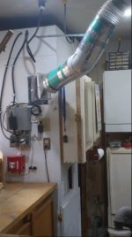
Height of duct connection at CV1800

sreilly24590

New member
I'm trying to layout the installation and getting the height of the actual duct connection is important as I have a few doors and windows to go in front of. I'm installing in a basement and it looks like the better install locations are about 20' away from the separating shop wall. I'll end up enclosing the unit in a insulated closet for noise control but I'm trying my best to get 5' of straight pipe from the cyclone before transitioning up to the ceiling height without blocking my outside doorway. So with the actual accurate height I can pencil in the measurements and see where I need to place the unit at a minimum. I hope this makes sense. Any information would be great.

Thanks,
Steve
 
sreilly24590,

I offer some observations from my CV1800 installation in 2015.

I followed a duct work layout plan that precluded 5’ of straight pipe at the cyclone transition. A 5’ straight run would have created other problems for my layout. Therefore, I used a 20” length of straight pipe at the cyclone intake. I figure the 20” pipe results in about 30” - 36” of straight run to the cyclone body.

I have good separation and suction. I not only enjoy 100% separation of larger debris like planer shavings, but also excellent separation of fine sanding dust from the drum sander and downdraft sanding table. However, had the straight run into the cyclone been 5’ perhaps separation of the fine dust would have been even better.

For reference, the distance between the bottom of the cyclone intake, where the dust pipe connects, and the ceiling is about 30”. This 30” includes a motor ventilation space of about 3” from the top of the motor to the ceiling. The distance from the bottom of the cyclone intake to the floor at the cyclone intake is about 6’. My ceiling height is 102”.
 
Thanks jsbrow,

That helps a bunch. My ceiling height is just a tad taller at 104" so we're very similar. The door is my biggest challenge. As the right side, looking out, is the only active door I have a bit more room to work with. From the corner to the left side of the actual french double door is 72" and I pick up an additional 30" for the inactive door. This is why I want to build a temporary stand for the unit before any piping is done and wire run. I really want to nail down the most optimum location for the very best performance. I may be getting too particular but I'd rather do it once right than multiple times wrong. Sort of like "measure twice cut once" analogy.

Thanks again
 
Steve, I'm in the process of installing a CV1800 in my basement shop and have had to pay a lot of attention to the dimensions of the unit because of my very low ceilings. For me, all of my measurements have been from top-down starting at my floor boards above the ceiling joists. (I will be lifting the motor up between the joists using a free-standing stand for the cyclone.) As best I can determine from scale dimensional drawing Clear Vue provides, you have exactly 24 1/2" of vertical space from the top of the motor to the bottom of the intake inlet. But, according to Cathy at Clear Vue, this distance can be varied +/- a couple of inches depending on how much length you allow the all-thread hangers when mounting the blower assembly off of the motor. If you make hangers shorter than the instructions specify, you can gain up to 2" in vertical drop from the top of the motor. What you give up is the easier access space to fit your fingers in between the motor mounting plate and the blower housing to tighten up the mounting blocks.

Dimensional Drawing: http://www.clearvuecyclones.com/inde...d_attachment=1

One other item needed for calculating your straight run allowances: the intake inlet is set at an angle 11 degrees to the cyclone body according to Cathy.
 
Last edited:
Rushton,

If that's 11 degrees up that's an advantage and I had not seen that. Hopefully after a trip to town tomorrow I can get some measuring done. I'm using some 1-1/2" mesh nylon strap to hang the duct, the kind we used in HVAC for hanging some duct. It allows for some vibration and movement without noise or stress. I also picked up a roll of 24 ga. bare copper wire and a roll of metal duct tape. The wyes and 22-1/2s are sitting in the basement as is the 60' of 6" PVC pipe. Cut the top of the 30 gal galvanized trash can and installed the 6" fitting, a 6" round duct take off with an adhesive base that's also sheet metal screwed down and taped. Installed the electrical sub-base months ago. Glade I had the HVAC experience which included a ton of electrical.

Thanks again for the post.

-Steve
 
sreilly24590,

I am not sure what you mean by temporary so this reply may be of no value. If you want the CV1800 portable (that is able to disconnect and occasionally move the CV1800 from the duct work) then perhaps my approach to portability can give you some ideas.

I wanted the ability to pull the CV1800 out from its normal home in a corner should I ever need to service the unit. I elected to make the CV1800 “portable” by erecting a tall cabinet set on castors to house the unit. A short pipe was connected to the CV1800 intake. A 45 degree elbow connected the pipe from the intake and to an 8” length of pipe. A short piece of smooth walled 6” diameter Flexaust flexible hose connects the 8” length of pipe to a second DW CV1800 Connection (360x640).jpg 45 degree elbow at the ceiling and to the permanently installed duct work.

If I need to pull the CV1800 out of the corner, the flex hose can be discounted and the castors allow the unit to be rolled out.

I attached a photo that shows my installation.
 
So after a bit of "what if's" and hesitation I decided to mount the motor assembly bracket in the location I thought was best. With the help of my neighbor we set the motor assembly and I proceeded to finish the assembly of the unit. A few minor adjustments such as the 6" inlet on the trash can had to be cut down at least 5" and then crimped to allow the 6" flexible connection, not a big deal. The attachment of the cyclone to the fan housing was something I really haven't seen clearly explained in the instructions but knowing I had the screws and a download of Marc's "The Woodwhisper's "install of the system it was easy to see although it meant taking the fan assembly down so I could reach inside to install the 6 screws. Another minor, although awkward for one person, task to do. Wiring in the pigtail is simple as long as you read properly the instructions. They say to wire according to the motor plate which shows CCW (counter clockwise rotation) and what's really needed is CW (Clockwise rotation). Evidently the diagram on the plate has changed but it is correct in the instruction manual. The control panel is mounted and simply needs the 30 amp feed from my sub-panel and while I'm at it a new 120 volt circuit for the remote control. It's almost as easy running two wires at the same time then one and I'm shy on outlets in the unfinished basement side that the shops not on.

I did take one 10' PVC pipe and hang temporarily by using two large heavy duty ties straps connected and hang from a few nails in the floor joists. This allows me to "see" where the pipe my interfere with my active door and to my surprise I can get a bit better than the 11 degree rise bu simply raising the pvc pipe far end. The way I know I'm slightly more than 11 degrees is the pipe is inserted slightly more on the top of the inlet adapter but probably less than 1/2" more. That said I can cut the pipe 5' from the inlet adapter and 45 degree up towards the ceiling and avoid raising the pipe higher than the 11 degrees. From there it's a matter of hanging properly, I'm using 2" wide nylon web strap, and running the rest of the pvc line, take-offs, and installing the blast gates. At this point I will like only have two machines that are stationary, the tablesaw, which I can pivot if needed, and the mitersaw station which will be close to 8' long when finished. The jointer, 19-38 drum sander, planer, bandsaw, drill press, and router table are all on wheeled bases (less the drill press) and can be moved into whatever place is best suited for the size of the material they are using at the time so I'll have probably 3-4 drops with blast gates at various optimum locations in the shop to hook these up to when needed. My thought is to minimize the use of flexible hose as much as possible but also keep tripping over these obstacles reduced as much as possible so at wall locations and maybe at the two support posts the shop has. The tablesaw will need the drop to come down away from the right side auxiliary table and the run the floor behind the saw to connect to the dust chute. I also need to wire in the bin level indicator. A fellow friend and woodworker is coming over to compare notes on where we think the best location for the drops would be. Two heads are always better than one and sometimes others see what we fail to even though it's right in front of us.

After this is said and done I'll build a small closet to house the unit less the filters to reduce the unit's noise level. Now to find a nice clean way to cut the 6" PVC straight. I may try the 12" compound miter saw with the blade that came with it rather than the nicer one I installed. PVC should cut well if cut slowly and held steady. If you try to power through it too fast it may well kick back or worse even crack or shatter. I'll post a few pictures as the unit is now after posting this message. I already almost lost this so better to post and add pictures later.

-Steve
 
So as promised I've added a page to my astronomy website to add some pictures of the CV1800 as far as it's come along. Today should finish all wiring and some additional PVC pipe layout. We'll see how well this pipe cuts and hopefully get the pipe closer to the ceiling height. The direct link is http://astral-imaging.com/woodworking_shop3.htm One thing I failed to mention was needing to shim the backside of the mounting bracket. I found the unit was leaning toward the wall and at first thought this was intended but after looking at the bracket closer I noticed that the angle was small at the bracket but enough to cause the unit to be less than perpendicular and maybe it's anal but it was something easily fix by simple shimming the bracket very slightly using some 1/8" shims I had made for a project before (hanging shop door). Propping the unit up using a 2x4 in the front just enough to move the bottom of the bracket off the wall to slid the shim in and tack with a small nail was all that was needed and it looks much better, even though you'll won\'t see the unit when it's enclosed eventually. I also used two #10 wood screws to secure the motor assembly to the slot in the bracket so it can't possible slide or move by vibration. The slots are there and I figured what the heck. I used the front slots only as the drill would have a hard time getting to the two back ones now that the unit was assembled. These two should be plenty

Thanks again to all who have assisted and any suggestions you may have.

-Steve
 
Last edited:
sreilly24590,

I am glad that you solved the door clearance problem. After reading your two most recent posts, I offer two comments. Hopefully they are helpful.

1. I found cutting 6” PVC challenging. I tried the bandsaw but do not recommend this tool. I successfully cut several pieces of PVC pipe at the bandsaw until, as I neared the end of the cut, something went wrong and the offcut shot unexpectedly across the shop. Therefore if using a power tool like the chop saw, ensuring the pipe remains perfectly perpendicular to the blade though the entire cut could avoid a mishap.

I cut most of the pipe with a reciprocating saw and metal 8” blade. I built a fixture to hold the pipe. The fixture featured a narrow slot to keep the blade running true. It worked reasonably well, but some cuts were not perfectly square.

2. From the photo, the mounting brackets appear to be attached to wooden studs. When the CV1800 is running, any vibration may transfer through the studs, to the framing top plate, and up into the floor joints.

This transfer of sound might be avoided if framing lumber (to which the CV1800 mounting brackets are attached) is directly attached to the concrete walls and kept independent of the home’s framing. This suggestion is based on my belief that the mass of the concrete will absorb vibration rather than transmit vibration.

Good luck in developing your layout and the installation of the piping.
 
jsbrow,

Valid points. I do have a Sawzall and large enough blades so I'll have a go at it and see who well that works. I know on a lot of new builds I've worked when I was active in HVAC the plumbers used a chop saw on most 4" PVC but I can't speak to any issues they may have had.

The mounting bracket issue is a wait and see. The nearest block wall is 15' away and that's going to be an issue in itself. We use to use cork/rubber isolators on commercial HVAC equipment and I could possibly use this between the framing and mount by using longer lag screws but at this point I'll wait and see what noise/vibration issues I may have and address from there. But it is a valid point indeed. The other side of this is that the normal hours this would be used is during the day when the vibration, if any, may not even be noticeable. I'm very unlikely to use the shop while my wife is sleeping.

-Steve
 
So I've progressed slowly as I plan on the go. I do have a basic layout but it is evolving as I go. I have to admit that using the 12" compound miter saw to cut the 6" PVC has been easy and without issue. I do clamp it and cut slowly holding the blade guard back as I start the cut. I also find that as expected I need to rotate the pipe at least once to cut through so you can either use a stop block or other method to make certain the length is the same after rotation or rotate enough so that you can match the blade in the existing cut and continue. I did the later and found two rotations did the trick and the cut was clean and even. Two suggestions: don't cut this inside if at all possible. My pipe is greenish blue and I had small bits of this stuff all over my shop. My home built work bench is adjustable and on wheels so I next rolled it outside and made the other cuts. Afterwards I used my air compressor to blow the PVC chips off, which really aren't chips as they are way too fine and more like small rectangular shavings which are very static prone and cling to everything including clothing. Messy but clean and effective cuts.

I've gotten past the french door and am about 7' from the separating shop wall with one wye used to branch off for the router table connection which is through the wall. I am using 26 ga. adjustable metal HVAC ells which is how I eliminated the 11 degree rise from the cyclone attachment. I ran the 5' straight pipe and then used the adjustable ell to make a 90 degree turn (minus the 11 so I guess in practice it's a 79 degree ell) so that the remaining pipe would be parallel to the ceiling joists. I was surprised at the sound level before and after hooking up some of the pipe. After running the pipe it was much quieter.

So with the 6" through the wall for the router table I used an adjustable ell and connected my 6" flex and then the 4" flex I've been using on my ShopSmith dust collector. I had the straight end of the wye capped off. Hey, I had to see this thing get it's first taste of sawdust:) Both flex lines are clear and I was amazed at how much sawdust it was getting out of the tablesaw without it even running. So I guess it was cleaning up the cabinet sawdust laying in the bottom. And then to see it swirling in the cyclone suspended and that 30 gallon heavy galvanized can raising up off the floor a few inches. Not entirely sure why that happened as I would have thought that would be positive pressure. BUt indeed the sawdust is collected. One mistake was not rotating the filter connector enough to take it to the left back corner but to correct that means lifting the motor assembly and unscrewing/rotating/screwing the adapter back in place and that's way too much work for me to do by myself. It's easier to enlarge the enclosure another 6" to accommodate the mistake.

So I'm partially piped, picked up the 2x4's and rockwool sound proofing insulation for noise reduction although I don't find it offensive upstairs directly above the unit. My wife and I found we didn't need to increase the volume of the TV when the unit is running but I'd rather dampen it now and make the enclosure to get the lowest noise level possible. The enclosure will be "C" shaped and attach to the existing exterior wall in the basement. Rather than attach it permanently I'll use large eye hooks to hold it tightly in place and have two access panels to get to the filter cleanout and the can to empty the sawdust. When time comes to blow out the filter or if I should need to service the unit I can unhook the eye hooks and slide the enclosure back. It too is a work in progress. I've consider making the access doors hinged or just take the screws out holding it in place. I'm incline to hinge the doors. As for the air from the filters I'm going to make a air chute (duct) and run that from the top by using a ceiling joist as a duct to move the air out of the enclosure. I just need to use some 1/4" plywood and span the ceiling joist to create the duct and let the air follow that path. That will also help dampen the noise.

So far so good. Just need to get the main line in the shop, 45 over to the location for the tablesaw drop, continue to the far wall and a drop for the miter saw bench, and one on the right and left for mobile tools such as the jointer, drum sander, drill press and so on. I figured on 5 drops total and that's looking about right. The miter bench is being made so I can also place my 13" planer on it and use the tables for infeed/outfeed so they will be a connection for that as well.

-Steve
 
Steve,

I would recommend that you use a 6" Fernco Connector at the junction of your straight pipe to the cyclone inlet. Here is a link to one from Lowes. They handle slight angular offsets very well and should fit over both end and eliminate any leaks. Hope this helps.

Rob
 
Well today proved a bit perplexing. I ran all but the last two take-offs and decided to try connecting the blast gates to the 3 take-offs and discovered they connect great to the SDR35 pipe but not even close to fitting on the flexible 6" tubing. I was advised that the answer has been to take a 6" section of pipe and use the band saw to remove about 1/2" and re-glue the pipe. Now it should it the flex but I have to admit I have no idea how it would now fit the blast gate that it originally did fit. Seems it would be too loose now. Now I do have a few 6" 26 ga. adjustable HVAC ells that I can crimp enough to fit the flex over and just a bit to make a short piece of 6" PVC fit as well. My thinking is this might be a better solution. The crimped adjustable ells can be taped inside (metal tape) to cover any very small gaps made from crimping and make the surface smooth again. They could also have copper wire attached and be grounded to adjacent copper plumbing for any static discharge.

Any better ideas that worked for you on making these flex connections?

Another thing I noticed is that my 30 gallon galvanized trash can rises off the floor when the unit is running. It as if it's being sucked up and I would have thought with the sawdust coming in it would be somewhat pressurized. What am I missing here?

-Steve
 
I noticed is that my 30 gallon galvanized trash can rises off the floor when the unit is running. It as if it's being sucked up and I would have thought with the sawdust coming in it would be somewhat pressurized. What am I missing here?
The trash can is on the suction side of the blower and therefore the flexible connection allows the can to be lifted due to the difference in pressure from outside to inside. It is a good indicator that you have a tight seal on all of the bin joints and connections, a must to insure good collection and no bypass of dust into your filters. The incoming dust is within the low pressure space and simply drops due to gravity into the bin while the air sucked into the cyclone moves back up into the inlet of the blower along the central axis of the cyclone.

As for flexible duct connections, I found that removing a turn or so of the wire coil and some heat from a hair dryer would allow the flex to stretch enough to be pulled over PVC pipe (I use the thin-wall D-2729 pipe of the same exterior diameter as your SDR-35 pipe). I've also used the Shop Fox wire hose clamps that straddle the flexible hose wire for a good tight fit.
 
Good tip McRabbet but how do you remove the encased wire? I'm guessing cutting the plastic at intervals and removing (sliding) the wire out? I'm really surprised with as many systems are out there no-one has made a reducer like coupling to accommodate this need task easily. Even a fitting like my 6-4" reducer fits inside the 6" PVC and has a ridge as a stop so if the 4" side was the same as the flexible hose interior you could slip it in and secure with a hose clamp. It would in essence be a 6" hose coupler.

One thing I have learned is that using the miter saw to cut the PVC is fast but extremely messy. There are a ton of very small diagonal bits of PVC for each cut and it should be done outside. Not sure if they are environmentally safe but I do use the Cyclone to suck them back up. Had I known this before I might have taken the time to make a hood for the saw and try to capture them directly like I will for the miter saw station I'm going to build.

Overall this has certainly been an education, some fun, and a lot of soreness for this aging woodworker. Two people would certainly make it an easier install as suggested from the beginning. Now if my 37 year old son were living closer.......

-Steve
 
So I thought I was making good progress until I started building the closet for the CV1800. Yesterday my heart sank as I looked in the cleanout and saw it was full and then some. This wasn't fine dust but rather straight from the jointer. Before that it seemed to be working as expected but I have been using it heavier than before with cutting panels, 2x materials, dados, and running the 8" jointer. I only have one gate open at any time and all drops have blast gates although several aren't completed runs yet. I have 2 drops that will both wye off for 2 connections each that are waiting on various stages of project builds, ie miter station. As messy as the shop is now I really didn't want to post any pictures yet but it's the best way I know to convey the status of the system. And I have double checked all connection of pipe which is held together by 3" metal duct tape, checked the rotation of the impeller (CW) as indicated by the arrow on the enclosure and if you were looking down from the top it is CW. I do see some fine dust on the impeller enclosure, throat to the filters, cleanout, and probably need to check all caulked joints. This would have been far easier before building the closet but I used screws to be able to disassembly if needed. I put up a page on my website showing a sequence of pictures showing what has been done so far and the results of last nights discovery. Please look at http://www.astral-imaging.com/woodworking_shop4.htm . Any suggestions very welcomed.

-Steve
 
So re-reading the documentation has a few hints. 1st my connection to the collection bin (30 Gal. Galvanized trash can) may not be that tight anymore. Before I would actually see it raise a few inches off the floor when running where now I don't think so. The assembly manual mentioned using a rubber sealant strip under the lid where the can meets the lid and I don't have this. It also mentioned sealing the 6" hose with caluk and in both connections to the can lid and cyclone it is simply slide on but appears tight. I'll correct both of these items and see if that makes a difference. I also seem to remember a black rubber grommet in the cyclone assembly and it looked like where someone might take an air reading but I'll have to double check that.

-Steve
 
Steve, according to Clear Vue, that black grommet on the cyclone itself is there to clear out a dead spot inside the cyclone itself where dust would otherwise collect. I think your onto a good track checking and fully sealing your dust bin collector trash can. Everyone says that needs to be air tight or dust will go into your filters. Good luck!
 
Back
Top