Blower modification...

Erik

New member
Merry Christmas to all

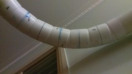
After using my cyclone for two years I was tempted to make a change to the blower. After reading a lot of info on the net I found that fans produce a lot of noise by themselfs and changing the shape at the tip of the wing has a great effect on the sound they produce. The present small rounding on the wingtip is just a little example.
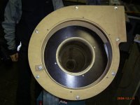
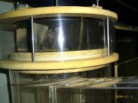
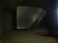
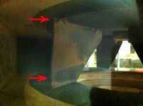
I noticed that the distance between the fan and the bottom of the blower was about 28mm. I wanted to know what would happen if I made the gap smaller like 2mm. (see photo's)
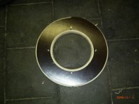
So I made a disk of 430mm (17in) with a hole in the middle to fit inside the blower. The thickness 27mm (18+9mm) made of two sheets of multiplex.
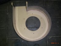
Rounded the edges and screwed the whole thing to the bottom of the blower.
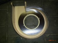
I put the cyclone together again and found that getting the gap even on all sides was not that easy.
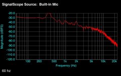
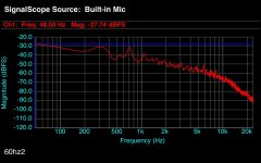
I started the cyclone and the sound was completely different. Much softer and less irritating. As far as I can tell the sound not as loud and I have more sucktion.
I have no scientific measurements but the overall result is a cyclone that is to me much better.

Any comments?

Erik
 

Attachments

  • R0010067s.jpg
    R0010067s.jpg
    116.7 KB · Views: 3
  • R0010068s.jpg
    R0010068s.jpg
    102.1 KB · Views: 3
  • R0010069s.jpg
    R0010069s.jpg
    118.6 KB · Views: 4
  • R0010070s.jpg
    R0010070s.jpg
    105 KB · Views: 3
  • R0010073s.jpg
    R0010073s.jpg
    144.4 KB · Views: 3
Hi Erik, hi guys. First a few words off topic.

I've just registered, but have been lurking for a while as i'm building a system - although i bought a fan and 16 in impeller from Ed Morgano.

So hello to you all, and thanks for your help. I've just finished specifying the ductwork in 6 in, it's coming out at around 5 - 6 in WG to each machine using Bill's calculator. My shop is smallish - 8.5 X 5.3m, and the cyclone is in an adjacent room.

Your posts have been of particular interest Erik, in that being in Ireland i also had the 50Hz power (230V single phase in my case) and filter sourcing issue.

I'd like to thank you as i've got sorted out in both areas. Donaldson UK for the filters - a direct result of your postings. I could raise no interest from the other big player, but D had as in your case a local sales rep who got stuck in. Nice people too.

On the single phase 50Hz issue i struggled for a while, but it eventually turned out that Omron have a fairly new model V 1000 4kW single phase input inverter that's spot on at just under €400. Expensive enough, but nothing like the €650 - €1,000 quoted by the only other two suppliers.

One big advantage apart from bringing me back to 3,450 rpm (i didn't like the way the 2,850 fan curve was starting to tail off at around 9 in WG - it didn't seem to leave much room for error) is the soft start as it reduces my peak current draw significantly compared to a single phase motor.

On your experiment. I'm an engineer but have no real experience beyond a basic training in this area. That said just thinking about it the impeller must create a ring of (relatively) high pressure air around its periphery, while at the same time developing suction in the area of the inlet.

It seems likely that a large clearance linking these areas could lead to leakage and recirculation. It seems likely also though that a considerable layer of entrained air probably whirls around in this gap with the impeller - that leakage might really only get going when the gap gets big enough.

What size gap that might be i haven't a clue, but looking a the fan photos on Cincinatti fan SPB blowers catalogue linked by Bill P (the one containing the fan curves for different impellers) suggests that they use a narrower gap - maybe 1/2 in.

On the negative side i could image that getting too close could choke flow from the inlet through the vanes - by somehow restricting flow through the vanes. Either as a result of turbulence, or of maybe some sort of boundary layer intruding.

Bill's fans seem to deliver good efficiencies anyway, the question is perhaps how much the noise can be reduced without paying too much in airflow.

By the same token Cincinatti (who are selling to industry and are probably bothered about noise) don't seem to be very bothered about rounding or clipping the corners of their fans, although the outer surface of the fan housing has a fairly decently radiused shoulder. (possible to ease forming of the sheet metal housing halves though)

One way or another turbulence in these sort of things generally tends to be associated with noise and inefficiencies, except in specific situations where e.g. a standing wave is being used to modify flow. So if you're getting less noise you're probably (a) more efficient, or (b) (the rub) moving less air.

If you were to shove one end of a simple water filled 'U' tube into a duct for with/without it should show what effect the change is having on the level of suction developed by the fan.

My CV Max 16 in fan from Ed has a square strip of about 8mm square plastic screwed to the inner face of the plastic band that forms the outer vertical element of the housing near to the gore point. (the sharp bend in the plastic) Ed says it's optional - it drops the sound level by about 10DB at the expense of a small drop in output. This by creating a sound wave that cancels that produced at the gore point. I've not seen this mentioned elsewhere.

Despite the 16 in impeller the housing is taken from 24 in square pieces of MDF which is an inch or two smaller than what Bill suggests in his material - Ed reckons this has no effect on output either, but has the obvious advantage of giving 2 no. from a 4 ft wide sheet of MDF.

The other silencing option i've seen Bill describe is a glass wool packed canister/silencer fitted in the outlet duct between the fan and the filters.

I wonder how effective lagging the fan and outlet duct with a sound deadening material might be?

Pardon the length, and thanks again for your help.

ian
 
Ian,

I am glad that I could make a small contribution with my work on the cyclone. It was indeed the information that I found on the Cincinnatifan.com site that gave me a better insight into the dynamics of a blower and ducting.

Erik
 
Last edited:
Some addition information after a few hours of use of the new setup.
1- I use about 10-15% LESS current (for the same configuration)
2- The dustpattern on the back of the vanes has changed (see photos) I can only suppose that there must be less turbulance so the fine dust can now stick to the vane. (The photo after is the one with the plate fitted).
It seems there is still room for improvement - there are still spots that catch turbulance.
 

Attachments

  • RIMG0033s.jpg
    RIMG0033s.jpg
    57.1 KB · Views: 2
  • IMG_vane2.jpg
    IMG_vane2.jpg
    100.2 KB · Views: 2
Last edited:
And here are some measurements from an uncalibrated iphone with some FET software. It shows that the modification changes the dominent frequency and the total soundlevel is down by about 10dB.
The charts are for 3450 rpm. the second one is for the new setup.
 

Attachments

  • IMG_60Hz.JPG
    IMG_60Hz.JPG
    108.1 KB · Views: 1
  • IMG_60Hz2.JPG
    IMG_60Hz2.JPG
    122.4 KB · Views: 1
It's clear it's having a pretty pronounced effect Erik. It'd be nice if there was a handy way to get some air flow figures.....

ian
 
Update 18 months later

Update 18 months later

For those that are interested in the modification of the blower here is an update picture of my blower. You can see the pattern on the vane. Interesting is the pattern on tip at the top of the vane. In contrast to the rounded corner at the bottom the top is not rounded. and you can see a clear vortex pattern. The red arrows show the parts concered.
In some post I read that Ed had added the rounded corner at the bottom of the vane to reduce the noise. So now I am suggesting the he should do the same with the top corner(s). It would also reduce the noise the vanes make.

Just my 2 cents

Erik
 

Attachments

  • IMG_1418-20.jpg
    IMG_1418-20.jpg
    217.7 KB · Views: 2
Hi Erik. I've just started up my own 16in impeller install, and have put up an album of build photos in the CV1800 & CVMax Installs album.

My system is a little unusual in that it's mounted on the floor of a loft over my office/sharpening room. I've been impressed at how smoothly it runs (the CV 16in impeller is well balanced), and have got a very decent reduction in by soft mounting the whole blower and cyclone assembly.

That's in effect a double soft mounting as used in a spin dryer - the unit is mounted via the usual studs and rubber hose sections to the mounting bracket, but the bracket is isolated from the loft floor using polyethylene packaging foam pads and gas tube over the screws.

When optimised this arrangement means that any movement in the main assembly cancels the movement in the chassis/mounting. I don't know how well my version works, in that I don't know if the stiffness of the two mountings is such as to deliver this effect.

I also have a silencer/cylindrical attenuator in the blower exhaust, the blower has Ed's rectangular strip screwed to the housing near the outlet.

To your point. The impeller sounds pretty smooth which might suggest there's not too much turbulence while there's a blast gate open. On the other hand when all are close there's a definite 'fluffing' note that comes in that suggests that maybe there's a bit of cavitation or something.

There's also a tendency (gates open or closed) to a slight rattling sound from the silencer which is sheet metal and packed with mineral wool - despite all of the construction being screwed tight together. Which possibly suggests that there's a fair amount of buffeting/turbulence in the exhaust air flow.

ian
 
Erik,
Would you make any adjustments to this modification, if you were to repeat it?
Do you think there is any benefit to covering more of the bottom? Was that outside round over that gradually faded at the one 'corner' done on purpose?

Thanks,
Rob
 
RMason

Yes I want to make some more adjustments
I would like make the disk smaller: the same size of the fan.
The main idea is to get the air through the fan straight out of the inner tube. Ideally I would have the fan fitted with a bottom plate (with a 9" hole in the middle) and have the inner tube right up to the fan, at the same time I would increase the size of the blower housing output to reduce the back-pressure.

I do not think increasing the size of the added disk is any good. It would just decrease the output size and add to the back-pressure.

The rounded corners on the outside of the added disk are to get the air smoothly from the fan out into the blower-housing.

I will try a few different configurations as soon as I can get the right instruments to measure the CFM, SP and Amps. real soon now..:)

I will keep you posted

Erik
 
I added a similar ring to my blower housing also Erik. My amp draw increased with the ring and I noticed more suction at my machines. Mine is larger than the impeller but I did it like that to try and close of the gore point to limit the amount of air that might get recirculated. As a side note the exhaust on my blower is 55.5 sq. inches.
 
Update?

Update?

Erik,

I'm just setting up my own cyclone soon and have looked at this thread with interest. I am wondering if you have changed anything or found anything else out with your research? Is the added plate working still for you and would you change anything else?

Thanks for the information!
 
Pardon the multipart post....

1. I interpret the preceding posts as follows:

  • Minimizing the gap between the bottom surface of the blower veins and the interior suface of the blower housing will reduce noise and improve efficiency. If so, what is an acceptable gap?
  • Rounding the corner of the vien reduces noise. If this is also true, is the noise reduction gained worth the risk of imbalancing the impeller?
Though I am not a fluids engineer, as I was assembling the unit I thought that the large gap between the bottom of the veins and the blower housing was a bit redundant and likely to cause alot of turbulence. I was also thinking that the upper suface of the impeller should just fit into a recess in the housing such that the undersurface of the impeller plate is flush with the housing. Would this be a reasonable assumption?

2. Another thought about noise and air flow: My impeller creates a counter-clockwise vortex in the intake tube (when viewed from below), but the cyclone inlet creates a clockwise vortex in the cyclone body. To me this reduces the efficiency of the cyclone. When I purchased the cyclone I thought that the overall design was "handed", but it apperas that there is only a counter-clockwise impeller for both right and left hand cyclones. Has anyone tested the performance of right handed vs left handed cyclones each using a counter-clockwise impeller?
 
Hi to all,

Subject is very interesting, and I would like to share some thoughts. I am not acoustic engineer, but spent a few years working on measuring vibrations. I did some research and found something that I believe some will find it interesting.

My opinion is that to lower the noise, effective way is to lower it at source. So, where is the source and how is produced? Many of us realized that source is in blower, but how is it produced? First I read this article http://www.scribd.com/mobile/documents/32261459/download?commit=Download+Now&secret_password=

and realized that key term is BLADE PASS PRESSURE PULSATIONS. After that I found next article http://www.hindawi.com/journals/ijrm/2009/704845/ .

Maybe, the solution could be in adjusting the gap between impeller fins and enclosure?

Just my 2 cents.

Milosh
 
Last edited:
Eric,
I finally got around to making the 'ring' modification. I made the outside diameter 15 inches (well it ended up just slightly smaller), which is the diameter of the impeller.

I messed up on the inside dimension, measured on the wrong side of the the router bit. So my inside hole is 10 inches. The hole in the cyclone is 9 inches. But this does match the diameter where the impeller angles down. (said another way, my ring corresponds to the flat bottom part of the impeller).

So what do you think? Should I redo it with a 9 inch inside hole to match the cyclones hole? Could matching the bottom of the impeller actually be beneficial? Or doesn't matter either way.

My first thought was to start over but when I realized it matched the impeller, I thought I would see what you thought.

Thanks for the help,
Rob
 
Exhaust is the big contributor to noise.

Exhaust is the big contributor to noise.

My installation does not use filters; it vents directly to the outside. (See http://www.clearvuecyclones.com/Bullentin/showthread.php?t=1427)

When it was first installed, the noise level at head height 10' from the blower was 97db ... LOUD! As improvements were made, noise readings were taken, as follows:

Nothing on at all ... 5dB ... its a quiet shed.
Turn on the VSD (it hums) ... 10 dB
Turn on the Clear Vue:
* Naked ... no ductwork in and no exhaust ... 97 dB (ouch).
* 200mm HVAC duct to exhaust (about ten feet long) ... 78dB
* Add 300mm duct over the 1.5 M of 250mm duct that is inside shop ... 66 dB.
* Wrap three layers of thin polyester insulation (off-cuts) around blower and hold in place with a mastic-like material ... 62dB.

Given that a 10dB reduction halves the noise, there is a big drop from 97 to 66dB (it is now one eighth of the original level), and all that was done to achieve that was to use two layers of insulated HVAC duct to muffle the exhaust.

I understand that in America you must use filters, and that changes the solution. However, it seems pretty clear that the bulk of the noise comes from the exhaust, so noise reduction work should really start there.
 
That's interesting John. I'm guessing that on the stock CV install the filters to quite a degree act as silencers/mufflers - that exhausting through a steel duct ups the noise.

As below my install is not unduly loud (there's photos - see Ondablade in the CV Max/CV 1800 section), but the exhaust silencer (an actually fairly short at roughly 900mm long stock HVAC rigid metal cylindrical silencer/attenuator filled with a perforated 200mm bore tube and packed rockwool or similar is fitted in my 200mm dia exhaust duct - they are stock in HVAC and cheap, and normally longer only I didn't have room) was fitted before it was run - so I can't tell how much it contributed. My system recirculates through filters, or exhausts outside depending on how a blast gate is set - it's definitely quieter through the filters.

I don't have a noise meter, but do know that adding the the soft mounting later made a noticeable difference too - but it's screwed to a loft floor and so I can't be sure it would do the same mounted from e.g. a heavy masonry wall. It probably would because the floor is very solid and the location is right beside a supporting wall.

Does your fan have Clear Vue's silencing 'stick' screwed to the inside surface of the fan housing wall (the PET plastic) just before the exhaust? That's supposed to drop the noise a bit too, and suggests that CV's focus is the exhaust too....


ian
 
Last edited:
Nice installation, ondablade.

My system is a CV 1800. I used 6" PVC pipework for the ducting, and it is very quiet. The main line was designed to have but one 90 degree bend, but to minimise flow and pressure loss it was made up of six, 15 degree elbows (see pic). It seems to work very well. I'm told that metal ducting is noisier, but this is hearsay only. Mine is the only installation I have personally seen.

Bill's site makes the point that most of the noise comes from the exhaust side, which is why I started there. Even leaving the exhaust transition uncovered makes a difference (I tested it). The noise reduction achieved by those two cheap pieces of insulated HVAC ducting was as profound as it was pleasing. There is no PVC or metal tube in the exhaust system, only the HVAC ducting. I had originally planned to enclose the cyclone in an insulated cupboard, but gave that idea the shelf when the noise level dropped below 65dB.

My exhaust duct is ten feet long. Bill's site said eight feet was necessary to get good sound reduction, so I added a couple of feet. The noise from the exhaust (outside my shop) is about 73dB 3' from the outlet (no muffler), 64dB 10' from the outlet, 54dB 20' from the outlet and about 43dB 30' from the outlet. That noise has been transferred from inside to outside my shop, but it is not loud enough to annoy neighbours, none of whom are close to the exhaust. The noise level ten feet from the blower (inside) is almost identical to the noise level the same distance from the exhaust outlet (outside).

My experience is limited, but it seems clear that the exhaust side of the system is where most of the noise comes from. I thought the 250mm HVAC duct was a wonderful addition, but the noise halved again when I pulled a similar 300mm duct over the smaller one. Can you do something similar to your exhaust side? The HVAC insulated duct is dirt cheap, so it is worth a shot.

When I was in the Army we installed a 250 kVA diesel generator at divisional HQ as a power back-up. From memory, the engine was a six cylinder, six litre Caterpillar that ran at about 1,500 RPM. The air intake was a big insulated box (sorry, that's as technical as the description gets) and the exhaust was about 30M of insulated duct with a muffler in that line. From 5m away, you could barely hear that big diesel running. That installation taught me a lot about where the noise came from.

The insulation on my blower worked, and it could be done a lot better, but blower noise is marginal compared with the exhaust. Also, when my noise level dropped below 65dB I stopped work. My shop vac is over 70dB, and almost any machine I am using is louder. In addition, my most commonly used machines are the furthermost away from the cyclone, so the noise has ceased to be a significant issue.

I am measuring sound with an app for my android HTC phone. It works a treat. An associate here in Australia tested it against the expensive instrument at his workplace and they are in very good agreement, so it works well ... and the app is free.

Sorry, my blower is now covered, and I can't see whether there is a "stick" near the exhaust.
 

Attachments

  • IMAG0021.jpg
    IMAG0021.jpg
    45.6 KB · Views: 1
Last edited:
Ta John. Looks like you have tried to do it right too. The phone app noise meter sounds like a good move, I'll have to take a look.

Noise was a little late getting on the radar for me - somehow I only picked up that some saw it as an issue and were taking steps to reduce it after I had decided my layout. My silencer is fairly short because there's a branch down to the filter cabinet in the room below just after it.

That said i'm doing just fine - it's seems a bit quieter than the 1HP mobile bagger I had before. Don't underestimate the value of soft mounting either, that one is from experience too. (mounting engines) Anything that stops the transmission of vibration into structures will quieten it down.

The exhaust is definitely where the heavy noise is - it makes sense in that that's where all the high energy/high velocity flow is. The 'stick' is a roughly 5/16in square strip screwed to the inside face of the fan housing just at the start of the outlet - it's supposed to cause some turbulence that breaks up any pulsing of the flow from the fan.

It makes sense that PVC ducting should be quieter for this reason - much less inclined to vibrate. The problem here in Ireland is that (a) the size is not widely available, and (b) it was quite a lot more expensive than steel spiral.

Some of the US guys use Nordfab clip together steel ducting, that has some advantages in terms of easy assembly and re-usability. Expensive too though....

ian
 
newby

newby

I am new to this forum.
I am on Lumberjocks for many years.
I bought a used CV 1800.
I have neighbors all around me.
I installed it outside my shop and I build shed around it.
I installed a sound barrier.
Yet the noise is still too high.
What can I do?
Someone on Lumberjocks told me about a modification on the impeller. I am an engineer and I concerned about modifying the impeller because of the balance/vibration issue.
I read something on this forum about insulated HVAC duct.
Any help would be very welcome.
Thank you Bert.
 
Back
Top