DIY Bin Sensor Project, cheap!

Mark Lord

New member
A buddy was over using the shop this week -- we planed several hundred linear feet of spruce 2x10 for a project of his. And in the course of doing so, managed to overflow the bin/cyclone/filters twice (!).

A tip on recovering from this: First, empty and replace the dust bin. Then loosely connect a flex hose intake to the filter clean-out box, and let'er rip! Give the filters a few taps/shakes while it's circulating, and they'll come out fairly clean in short order.

After we finished for the day, attention turned to preventing future overflows. With the demise of the McRabbet bin sensor offering, I have decided to roll my own. This thread will document the materials and progress.

Previous efforts (eg. McRabbet) used standard garage door optical sensors. While readily available, they do cost a few pennies, and require some circuitry to interpret the pulsed output. I can easily cobble that kind of thing together, but there may be simpler solutions available these days.

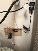
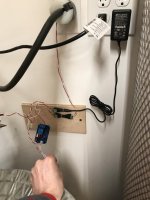
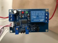
On Amazon, I found a 12V "Photoresistor Relay" board with sensor for about CAD$10, which should do the trick. It'll be here by this weekend. The plan is to mount that device on the outside/top of the bin lid, and tape/glue (hot-melt!) the sensor to either the clear flex hose there, or directly to the bottom of the cyclone itself. Most likely the latter in my case, as the setup here has only about 1" of flex hose between cyclone and bin lid (an extra tall bin). I'll put a 12V LED bulb on the side opposite the sensor, and wrap black tape around the circumference, shielding the setup from strong stray ambient light.

Both the bulb and the "Photoresistor Relay" board will be powered by a 12V/2A AC adapter, plugged into the 120V output from the CV remote control receiver. So it gets powered only when the cyclone itself is "ON". That same 12V AC adapter will also be used to pass power through the board's relay contacts to a 12V LED "flashing light" of the type intended to magnetically attach to the roof of a vehicle. These are readily available from Walmart, Canadian Tire, Amazon, etc.. for CAD$35-$50 or so.

When the light from the 12V bulb is interrupted by a pile of sawdust (due to the bin being full), the relay will trigger and the "flashing light" will illuminate and do its thing. I'll be mounting that device upside down on the ceiling of the workshop so that is easily noticed from anywhere in the shop. The same relay can also simultaneously be used to cut power to the cyclone relay if desired, shutting off the CV blower.

That's the plan -- the principal unknown at this point is whether or not some extra hysteresis is required. In other words, is some extra averaging or a delay needed to allow for momentary blockage of the beam? TBD. Stay tuned for updates, and feel free to contact me for direct links to The Exact Stuff I am using here.

Cheers
Mark
 
Last edited:
The Photoresistor Relay board arrived earlier in the week. There are two versions of this board from the same seller on Amazon Canada. One is just a simple darkness activated relay, with adjustable "darkness sensitivity. The other fancier unit costs an extra $2 or so, and has an onboard microprocessor and a second adjustment for "trigger delay".

I purchased one of each to experiment with, and have concluded that the simpler board is too simple for this application. It is completely analog, and thus "buzzes" the relay when the light level is just at the edge of a full trigger. The second board, with the microprocessor controlled delay feature never does that, and the delay can be set to a couple of seconds to eliminate false alarms when doing, say, heavy planing.

I have temporarily taped the sensor to one side of the bottom of the cyclone, and taped a set of three LEDs from a 12V lighting strip to the other side, with black tape behind them to block ambient light. I am using a 12V/3A AC-Adapter (also from Amazon) to power it all. In preliminary testing, the system works incredibly well!

The only glitch thus far is that the fancy board does a "lamp test" every time it is powered on -- triggering the onboard relay for about 1-2 seconds as a self-test or something. This means I cannot really power it from the cyclone relay feed as originally planned, because doing so gives a 1-2 second false alarm each time the cyclone starts up. Not good. But the solution is pretty simple: just plug it into a wall outlet directly, so that it is always powered on. Thankfully the power waste is minimal: the Kill-A-Watt meter says 1.1watts in idle state, so I can live with that for now.

The amber flashing light I ordered is taking the slow boat from USA to Canada -- got tricked by the seller claiming to be "Canadian", as otherwise I could have just picked one up locally for $5 more. So until that arrives (couple of weeks) I'm just using some 12V strip LEDs as the "bin full" indicator.

Photos coming soon. Total cost thus far is about $10 for AC Adapter, $12 for sensor/relay board, perhaps $1 for a 12V light source, $35 for the flashing light, or around $58 in all. One could reduce the cost down to $23 by using an ordinary light bulb (painted yellow?) or similar in place of the flashing light, but I *like* the idea of a flashing light!

Cheers
 
Last edited:
sensor_wiring.jpg


The sensor board and wiring. By zooming in, one can see the model number FC-66 on the circuit board for reference. I have both 2-pin jumpers installed. The one beside the blue relay puts 12V onto the relay common pin, saving me from having to run another wire for that. Power for the system comes in from the AC adapter via the red/black wired socket. When the relay switches on (indicating "bin full"), 12V power is applied by the relay to the yellow/black wired socket. The flashing warning light will get plugged into there when it finally arrives here.

The photosensor itself has been hot-melt glued (by me) to a small block of wood to facilitate mounting. The short strip of 3-LEDs is used to provide a light source for the sensor, the idea being to mount those on one side of the flex hose or cyclone bottom, and the sensor itself on the opposite side. I plan to tape/glue mine in place, but one could make simple brackets to wall mount them in similar orientations.
 
Last edited:
close-up.jpg Here is a closer, more detailed view of the board, wiring, and sensor. The black/green power jacks are a handy convenience, but one could instead just cut the plug from the AC adapter and twist/tape or solder all of the connections.
 
Last edited:
Okay, all installed now. I mounted the circuit board onto a scrap of plywood using hot-melt glue, and then screwed that to the inside of the DC closet wall. The AC adapter is plugged into the nearest outlet, with its power cord running through a hole into the DC closet.

The sensor and light source LEDs are hot-melt glued to the outside of the bottom of the cyclone -- not enough flex hose in my install to put it lower down, but it should be easy enough to tape in place on a system that has a few inches of hose between cyclone and bin.

For now, I've just got a bright strip of 12V LEDs serving as the "alarm", mounted to the ceiling in about the middle of the shop. Those will be replaced with the amber flashing cherry light when it eventually arrives.
mounted.jpg installed.jpg sensor.jpg leds.jpg
 
The setup above costs under CAD$25 as-is, without the flashing cherry warning light. This same setup can be modified to instead turn off the CV dust collector blower at the same time as turning on a 120V light bulb to act as the indicator. The only extra components needed are a 120V power cord, a 120V duplex receptacle, and an aptitude for basic electrical wiring. If you lack the latter, stop reading now.

1. REMOVE the jumper from the two pins adjacent to the chunky blue relay, disconnecting the 12VDC from it.
2. Also remove the yellow wire pictured above, and dispense with the yellow/black wired DC socket -- not used in this new configuration.
3. Break the tab between the two hot/black screws on the receptacle to convert it to "split duplex" configuration.
4. Wire the white wire from the power cord to the neutral/silver side of the outlet.
5. Run the black wire from the power cord to the middle terminal of the relay.
6. If your power cord has a green wire (ground), connect it to the ground screw on the receptacle.
7. Connect a new black or red wire from one of the two hot/black screws of the outlet, to the same relay contact that formerly had the yellow wire from above. This side of the outlet is where the 120V light bulb (or siren, or whatever) should get plugged in as the new "bin full" indicator.
8. Connect a second new black or red wire from the other hot/black screw of the outlet, to the remaining relay connection. This is where the CV remote control power/receiver brick should now get plugged into.
9. Done. Plug the power cord into a wall outlet.

Now everything should be working normally. When the bin fills up, the relay on the board will trigger, lighting the bulb, and REMOVING power from the CV remote control -- which will result in immediate shutdown of the blower fan.

Cheers
 
Last edited:
Another DIY sensor that is cheap and works really well is described in this thread on Sawmill Creek, I built it and it flashes the alarm every time the bin is a few inches from being full
 
Another DIY sensor that is cheap and works really well is described in this thread on Sawmill Creek

Yeah, I like that one, but it is not cheap! The sensor alone costs about triple what my current setup cost, and that's when purchasing it direct from China -- with 4 month shipping time to Canada (currently; used to only take a few weeks).
 
Last edited:
An update on this: I have since moved the LEDs and sensor down an inch or so, inside the lid itself, to get even earlier warning of an impending full bin. As a bonus, the LEDs now illuminate the inside of the top portion of the bin, permitting quick visual inspection of the current fill level without having to remove the lid!

This has worked out very well. Lots of planing this past week, filling the bin twice. Each time, the flashing indicator triggered sporadically at first, and then more incessantly as the bin filled to the top. Each time, I finished the board in progress, and then gave the bin a shake to settle the contents. Upon removal of the lid, the bin was evenly full up to within about 1.5 inches of the lid, with no significant overflow to the filter stack.

Well worth the small effort and modest cost involved!
 
Last edited:
Hi Mark, just joined the group and I have followed your instructions. When I cover the photo sensor the switch light comes on but I am not getting any voltage to light the strobe. Appreciate any guidance.
 
Okay, we should be able to get this sorted. The 12V output for my strobe comes from the yellow/black wire pair. The yellow wire is +12V, the black is Ground. The yellow wire is attached to the output from the big blue relay. I have both 2-pin jumpers installed. The one beside the blue relay puts 12V onto the relay common pin, saving me from having to run another wire for that. If the board you have differs in any way from this, then we will need to compare them in a much more detailed fashion to sort things out.

You should be able to hear the relay go "CLICK" whenever you cover/uncover the sensor. If not, then perhaps some adjustment of one/both of the blue/brass potentiometers is needed.
 
So I hear the relay “Click” and the green switch light comes on when the sensor is covered and does off when uncovered. I believe I have the same board as yours so there should be no issue there. I have attached a picture of my temporary set up which might help. But when the relay switches when covered I am not getting 12v from the connection on the right of the large relay. Not sure if I have the jumpers wrong or if it’s something else...
 

Attachments

  • 26E74C6B-9CBA-413D-AB2B-E4D5F690951F.jpeg
    26E74C6B-9CBA-413D-AB2B-E4D5F690951F.jpeg
    44.7 KB · Views: 4
  • F90BC685-C566-42AD-B435-E472CCC7BE6E.jpeg
    F90BC685-C566-42AD-B435-E472CCC7BE6E.jpeg
    49.3 KB · Views: 3
There are two double-pin headers on my board. Both of them have jumpers installed on them. The one immediately beside the relay (practically touching it) is the important one here. How do you know you are not getting 12V? If you have a voltmeter, then definitely use/trust it. But if the strobe is simply not working, then perhaps the two wires for the strobe are reversed somewhere?

Assuming you do have a volt meter, then check for voltage between ground (your WHITE wires) and each of the three relay contacts, with and without the sensor blocked/triggered. There should be "permanent" 12V power there on the middle relay terminal regardless of sensor. If not, then the jumper is missing or broken (easy fix). And with the relay NOT triggered, there should be 12V on the other unused relay pin. When the relay IS triggered, that power should move to the relay pin which your RED wire is attached to.
 
Mark, really appreciate the support.

I do have a multimeter and I am getting nothing on any of the 3 connectors on the right hand terminal block next to the relay.
 
Okay, that narrows it down. Here is my earlier photo, with the power jumper circled in black. Does your board have that jumper, or just two bare pins in that position? If different from mine in any way, please post a better photo of just the board for me. Thanks. controller.jpg
 
If you look closely at the photo I just re-posted, one can see a flat wire trace running up from the red wire terminal at left, across the top of the board (beneath the words "power time"), through the circled jumper, and then onward to the middle relay pin. That's how 12V normally gets to the relay outputs. If that trace is missing on your version of the board (they do change the designs from time to time..), or if the jumper connection is missing, then this explains why there's no power output on yours. The solution is simple: run a wire from the (+) terminal at top left over to the middle screw contact for the relay.
 
So mine seems slightly different. I have attached a better picture before I run +12v to the middle connector, in case you think different.
 

Attachments

  • DEAADEF7-8F78-4734-98B8-CF8DD8924573.jpeg
    DEAADEF7-8F78-4734-98B8-CF8DD8924573.jpeg
    74.6 KB · Views: 2
Excellent! The boards do seem to be quite similar, though perhaps yours is a slightly newer revision (surface mounted transistors as opposed to the through-hole ones on mine). I suspect that extra jumper on mine confused enough people that they just eliminated it for safety. Most people will be switching 120VAC with the relay, and it's a much less error-prone design the way yours is wired.

Cheers!
 
The photoresistor relay board I used is labelled with "FC-66" on the board itself. Amazon still has listings for this board, and for many similar boards. What distinguishes the FC-66 from the others, is that it has TWO screw-adjustable potentiometers (blue coloured) on-board rather than just one.

If this forum permits, here are links for Amazon Canada and USA:
https://www.amazon.ca/GEREE-Control-Photoresistor-Detection-Photosensitive/dp/B01I38TCOA/
https://www.amazon.com/Control-Switch-Photoresistor-Detection-Photosensitive/dp/B0797PV4H4/
 
Back
Top