You are using an out of date browser. It may not display this or other websites correctly.
You should upgrade or use an alternative browser.
You should upgrade or use an alternative browser.
Dust bin quantity sensor.
- Thread starter Guitarman
- Start date
")
Dust Bin Photoelectric Sensor
Dust Bin Photoelectric Sensor
Alan Schaffter of Washington, NC designed a bin sensor for his push through cyclone dust collector that works quite well. It is documented in two threads on the NCWoodworker.net website (members must be from NC, but you can browse the site as a guest). This link I've provided goes to one of his threads and the other is referenced in its first line. Because his cyclone is a push through design, his dust bin is under positive pressure, but it should still work with a ClearVue.
I bought a CV1800 in November, but have not installed it yet because of projects I had to complete by Christmas and two days after Santa Claus came, I had a bad fall and injured my shoulder (I have rotator cuff surgery next week). Nonetheless, I have designed my version of Alan's bin sensor and have made a fully operational mock-up. A PDF file is attached with the schematic.
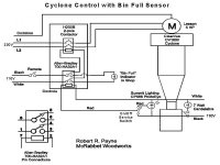
The unit uses the same remote and 2-pole contactor that Ed has on the products page to turn the cyclone on and off. It also uses the same low-cost Dusk-to-Dawn photo eye from Lowe's that Alan used and a switched 7-watt candelabra bulb located across the lower end of the CV cyclone as it connects to the bin. An Allen-Bradley "ice cube" relay (with an 8-pin base cost <$25) with DPDT contacts is wired with the normally closed contacts carrying the remote's 110V hot and common leads to the 230V contactor coil. When the bin fills to block the photo eye from receiving light from the candelabra bulb, it sends 110V down the Red wire to energize the A-B relay coil. This opens the contacts that feed the 230V contactor coil and diverts the power from the remote control to an indicator light in the shop. The blower shuts down and you know the bin is full. The two relays sit in a 6" x 6" x 4" deep Carlon box mounted near the Leeson motor. I put the switch in line with the candelabra bulb to shut it off to kill any false starts when I empty the bin (the photo eye must stay dark if you've forgotten to click the remote transmitter to Off!). Total cost is less than $50 above the cost of the required remote and 230V contactor.
When I get a chance to take some pictures, I'll post them here, too. But truthfully, Alan should get the credit. When you read his threads, be sure to read all the way to the end -- he gets kudos from Bill Pentz himself.
Hope this helps you and others here as well.
Dust Bin Photoelectric Sensor
Alan Schaffter of Washington, NC designed a bin sensor for his push through cyclone dust collector that works quite well. It is documented in two threads on the NCWoodworker.net website (members must be from NC, but you can browse the site as a guest). This link I've provided goes to one of his threads and the other is referenced in its first line. Because his cyclone is a push through design, his dust bin is under positive pressure, but it should still work with a ClearVue.
I bought a CV1800 in November, but have not installed it yet because of projects I had to complete by Christmas and two days after Santa Claus came, I had a bad fall and injured my shoulder (I have rotator cuff surgery next week). Nonetheless, I have designed my version of Alan's bin sensor and have made a fully operational mock-up. A PDF file is attached with the schematic.
The unit uses the same remote and 2-pole contactor that Ed has on the products page to turn the cyclone on and off. It also uses the same low-cost Dusk-to-Dawn photo eye from Lowe's that Alan used and a switched 7-watt candelabra bulb located across the lower end of the CV cyclone as it connects to the bin. An Allen-Bradley "ice cube" relay (with an 8-pin base cost <$25) with DPDT contacts is wired with the normally closed contacts carrying the remote's 110V hot and common leads to the 230V contactor coil. When the bin fills to block the photo eye from receiving light from the candelabra bulb, it sends 110V down the Red wire to energize the A-B relay coil. This opens the contacts that feed the 230V contactor coil and diverts the power from the remote control to an indicator light in the shop. The blower shuts down and you know the bin is full. The two relays sit in a 6" x 6" x 4" deep Carlon box mounted near the Leeson motor. I put the switch in line with the candelabra bulb to shut it off to kill any false starts when I empty the bin (the photo eye must stay dark if you've forgotten to click the remote transmitter to Off!). Total cost is less than $50 above the cost of the required remote and 230V contactor.
When I get a chance to take some pictures, I'll post them here, too. But truthfully, Alan should get the credit. When you read his threads, be sure to read all the way to the end -- he gets kudos from Bill Pentz himself.
Hope this helps you and others here as well.
Attachments
<<<__ Bøb __>>>
New member
I got really lucky and picked up a surplus Bindicator "tuning-fork" level sensor.
It sends a signal out to one leg of the fork, and as long as the other forks picks it up .. all is well. When the signal is interrupted, 2 NC contacts open and 2 NO contacts close. The contacts will carry 5 amps or so. Don't have it all installed yet, but when it goes in, I will set it up to automatically shut OFF the blower by breaking the power to the coil, and turn ON a flashing beacon. I figured if I only shut off the blower and didn't notice it, I would make a mess for awhile at whatever tool(s) were running. This thing is all solid-state and should last a lifetime. Since the forks are kinda long, I used a PVC 1.5: union to mount it to the lid of the dust bin .. .. that way, I can unscrew the nut a few turns .. remove the Bindicator .. set it in a wall-mounted holder .. then roll out the barrel and empty it. Without it being removable, it would be a bit difficult to get the barrel in & out.
It sends a signal out to one leg of the fork, and as long as the other forks picks it up .. all is well. When the signal is interrupted, 2 NC contacts open and 2 NO contacts close. The contacts will carry 5 amps or so. Don't have it all installed yet, but when it goes in, I will set it up to automatically shut OFF the blower by breaking the power to the coil, and turn ON a flashing beacon. I figured if I only shut off the blower and didn't notice it, I would make a mess for awhile at whatever tool(s) were running. This thing is all solid-state and should last a lifetime. Since the forks are kinda long, I used a PVC 1.5: union to mount it to the lid of the dust bin .. .. that way, I can unscrew the nut a few turns .. remove the Bindicator .. set it in a wall-mounted holder .. then roll out the barrel and empty it. Without it being removable, it would be a bit difficult to get the barrel in & out.
Bin Sensor Circuit Change to Consider
Bin Sensor Circuit Change to Consider
Rob thanks for posting the information on the Bin Sensor. I currently don't have a bin sensor but will eventually put one in. While reviewing the circuit for Alan's bin sensor with your modifications I noticed a possible change that might be beneficial to incorporate. If I understand the circuit correctly the lamp is on all the time unless you manually deactivate the power with the switch you added in series with the lamp. An alternative might be to eliminate the secondary 110 volt input source shown for the bin detector and instead use the 110 volt source applied through the remote switch for turning on the system. Doing this would insure the lamp is off whenever the remote power control is off. This would eliminate the heat from the lamp when you are not in the shop, may increase lamp life, and could allow the elimination of the switch you added in series with the lamp. Since the lamp should be off when the dust collector remote is off the light could serve as an indicator that the remote switch is on and should be turned off prior to empting the bin assuming it is visible while empting the bin.
I don't have this circuit so I could not test this circuit change to verify if it would works. My only concern is a possibility of some chatter or delay in the DC startup due to the PhotoEye output being in a possible undefined state during its initial power turn-on sequencing and lamp turn on at the same time you are trying to turn-on the DC.
Also, if your dust collector will be connected to the Bin with flex hose? Are you planning on installing the bin detector with the light sensing through the flex hose? I just wonder if the flex might be a problem.
Finally, I would appreciate any additional information on how your sensor works when you get everything up an running.
Thanks Again for your postings, ====> Al
Bin Sensor Revisit
Bin Sensor Revisit
Al T posted a suggestion yesterday that I will try -- feed power to the candelabra lamp from the hot side of the remote switch so that the lamp does not burn 24/7. I'm using a 7 watt cool burning clear bulb and although I haven't run any longevity tests, they last a long time (if anything, their life is shortened with frequent on/off cycles as evidenced from experience with electric candles in our windows during the holidays).
I am in the process of installing my cyclone now (after months of waiting until I was fully healed from my shoulder surgery) and in the interim, I did make one key improvement in the circuit and I've included an updated diagram here. I've added a "service switch" that will allow the "Ice cube" relay to be held in "bin full" mode while removing the bin and emptying the drum. It does not require that the remote switch be turned off and keeps the DC from having a false start.
To follow up on Al's suggestion, I'll use some leftover 14 ga. 3-wire non-metallic cable left over from hooking up my shop lights for the wiring between the sensor and service switch back to the main control box and use the Black lead to bring power from Pin 8 on the A-B relay to the Black side of the service switch. The white lead would be fed by adding a jumper between pins 1 and 2 on the relay. That would eliminate the separate 110V feed for the photoeye and candelabra and the switch for the lamp could be eliminated. Obviously it needs to be tested, hopefully by next week.
Added note: Al T asked about the placement of the sensor. I will install it in a "starter" collar; a 6" metal collar with tabs from the HVAC aisle at Lowe's. It is about 2-1/2" high and will allow the sensor and light to be placed behind clear plastic windows and still leave room for the flex to be connected. I'll seat the collar in clear silicone sealant and pop rivet it to the bin cover.
Attachments
Last edited:
Jim O'Dell
Moderator
McRabbit, looks great!! I do have one question: At the light source for the sensor, you have a switch at the bottom of the light in the diagram... is that right? Is that needed? If the 110 trigger power is switched, either with a wall switch or a remote, won't that turn the sensor circuit off? Thanks for the diagram! Jim.
Jim (and others),
The switch for the Candelabra lamp is not necessary; I put it in as a convenience switch. With the suggestion that Al T made in the 5th post to this thread, the power can be fed from the remote and when it is off, the lamp is off, too. The switch by the sensor is a service switch to activate the photocell for normal running or to turn it to the opposite side for servicing the bin (the middle position deactivates the circuit).
One key thing that users want to be sure of -- the Summit Photocell is one that has no built-in delay function (most commercial photocell units now incorporate a delay to keep them from reacting to headlights). I found them at both Lowe's and HD with the outdoor coach/post lamps rather than the electrical component aisle.
New Circuit Design for Bin Sensor
New Circuit Design for Bin Sensor
I realize that I am opening an old thread, but I thought I would post this new circuit that provides many improvements over the original, thanks to input from several people. First, here is the new diagram:

Note the following. 1) All 120 V power is fed through the remote switch and only the hot side is fed through the Allen-Bradley relay. 2) A 12 volt wall wart (not shown) is also attached to the remote switch output and +12 volt is fed through the other set of contacts on the A-B relay, but the normally open (NO) contacts. This 12 volts feeds an Amber Strobe Light (available on eBay for under $10 delivered!) that alerts a full bin. 3) I use 14/3 Romex from the enclosure to the base of the cyclone to connect the 7 watt candelabra bulb and Summit Photo Eye, with the red lead feeding 120 V back to the coil on the A-B relay. 4) I've added a "Relay Bypass Switch" connecting the upper set of NO contacts on the A-B relay to the coil on the Fasco H230B contactor. If you leave this switch closed, the Cyclone will continue to run following an Alarm condition. You'll want to keep the cyclone operating if you are in the midst of running a long board through your planer or a rip on your tabesaw. 30 seconds of chips in the bin is fine, but you could ruin a good board if those chips clogged your planer. When finished with the operation, flip the switch or turn off the remote and everything shuts down.
PM me for details or post questions here.
New Circuit Design for Bin Sensor
I realize that I am opening an old thread, but I thought I would post this new circuit that provides many improvements over the original, thanks to input from several people. First, here is the new diagram:
Note the following. 1) All 120 V power is fed through the remote switch and only the hot side is fed through the Allen-Bradley relay. 2) A 12 volt wall wart (not shown) is also attached to the remote switch output and +12 volt is fed through the other set of contacts on the A-B relay, but the normally open (NO) contacts. This 12 volts feeds an Amber Strobe Light (available on eBay for under $10 delivered!) that alerts a full bin. 3) I use 14/3 Romex from the enclosure to the base of the cyclone to connect the 7 watt candelabra bulb and Summit Photo Eye, with the red lead feeding 120 V back to the coil on the A-B relay. 4) I've added a "Relay Bypass Switch" connecting the upper set of NO contacts on the A-B relay to the coil on the Fasco H230B contactor. If you leave this switch closed, the Cyclone will continue to run following an Alarm condition. You'll want to keep the cyclone operating if you are in the midst of running a long board through your planer or a rip on your tabesaw. 30 seconds of chips in the bin is fine, but you could ruin a good board if those chips clogged your planer. When finished with the operation, flip the switch or turn off the remote and everything shuts down.
PM me for details or post questions here.
Some clarification after some questions by NickLazz may help others building this sensor.
I bought a 12 volt "wall wart" transformer and the corresponding jack through Digikey.com (Part No. T963-P5P-ND @ $6.98 and CP-038A-ND @ $0.47) which work well. The transformer supplies a regulated 12 VDC at 0.5A and the center tap is +12 Volts. That lead (from the jack mounted in the side of a 6" x 6" x 4" plastic waterproof enclosure) is connected to Pin 1 of the A-B relay while the other side of the jack gets connected to the strobe. You can mount the strobe on top of the WP Enclosure and extend its red lead to Pin 3 and the black lead to the ground side of the jack. Be sure the 120V White wire from the remote connects to the H230B relay, Pin 7 on the A-B relay and continues to the Photoeye and candelabra lamp. I did a search on www.action-electronics.com using "lamp strobe" and the third item is exactly the same as the stobe lamp I bought on eBay -- it has a 10-12" red/black pigtail, a gasket and two integrated machine screws to bolt it in place. Any color you want! Their power supplies should work, too.
A little explanation on the A-B relay. They come in two types with either 2 switches or 3 to fit an 8-pin or 11 pin socket, with many different coil voltage choices. They are in a compact shape, often called "ice cubes" by controls engineers. The 700-HA32A1 uses an octal socket (I used the 700-HN125 with screw terminals) and pin 2 and 7 connect 120V to the coil that activates the pair of switches. The other pins serve the switch contacts that are rated at 10 amps and are dual pole, dual throw switches with 1-3 and 6-8 in the normally open position. When the coil is activated (in our case by the light beam getting blocked and 120 VAC going down the Red lead to pin 2), the power coming to pins 1 and 8 is switched to pins 3 and 6. It you had an application needing 3 switches, the 700-HA33 series would be used with an 11-pin socket.
You can often find them on eBay or buy them at an electrical supply house.
The Summit Lighting CP688 Photoeye was purchased at Lowe's because it has no delay. Try the Orange BORG (Homely Despot) for one. If you cannot find one, you should be able to use one of the delay style found at Lowe's, like Utilitech EZ-346 for < $7.00. It will have a delayed action (the delay is so a passing car won't turn your yard lamp to turn off). It simply take a little longer for sawdust to block the beam, but you won't have false alarms, either.
Looks like it all works
Looks like it all works
Thanks for all your help McRabbet.
I tested my bin quantity sensor today after installing it and it works great. Have about a 25 second delay is all which will be fine because I have about 3' of 6" pipe from the bottom of the cyclone to the sensor.
I have not wired a warning light yet, I still may but haven't decided yet. I will probably just pull power off of the AB relay on 3 or 6 for that and splice into the neutral if I want one in the future. I figured just having it shut down should be noticeable enough, if not I'll add the light.
Anyway, thanks again. Very ingenious idea, and it really works. We'll see if the dust bothers it much.
Nick
Quick update
Quick update
One issue that I have come across is that the delay is on start-up too. I know some keep the light on at all times, but I didn't really like that solution.
The delay is about 25 seconds after I turn the remote on and the same for sensor full.
Not terrible, but what I may do is just wire the photo eye to a warning light and bypass the AB switch all together. Then again, I may be able to live with the delay, but I could see where it may be bothersome. If I come up with a solution that I like I will post my results.
Nick
Quick update
One issue that I have come across is that the delay is on start-up too. I know some keep the light on at all times, but I didn't really like that solution.
The delay is about 25 seconds after I turn the remote on and the same for sensor full.
Not terrible, but what I may do is just wire the photo eye to a warning light and bypass the AB switch all together. Then again, I may be able to live with the delay, but I could see where it may be bothersome. If I come up with a solution that I like I will post my results.
Nick
Resurrecting a great thread...
I finished my electrical hookup yesterday and everything working exactly as planned/expected. Wonderful design...almost perfect. Only complaint is the slight delay in the photoeye (20-30s), but thats not a big deal. When I mount the eye on the dust bin, I'll probably put it about 2/3 to 3/4 of the way from the top anyway as I'm not sure I want to wait until the bin is full to empty anyway.
A few things I did that I feel made the circuit better...
1) Put a hard switch in parallel with the wireless switch...this way I can use either the wireless OR wall switch to turn the system on/off. Only catch is that whichever I use to turn on the system, I have to also use that to turn it off. This limitation could be overcome with some added complexity, but its a non-issue to me.
2) Used a LED candelabra bulb. 2.5W is supposed to approximate a 15W tungsten bulb and is rated for something stupid like 15k hours or something. I've got it and the photoeye wired always on (as the diagram shows). Based on my utility bill, I figured this is going to add around $4/year to my bill. Ouch.
3) Wired the 12V DC power supply to the switched power...no need for this to be wired always on and leech extra power when not in use.
Resurrecting a great thread...
I finished my electrical hookup yesterday and everything working exactly as planned/expected. Wonderful design...almost perfect. Only complaint is the slight delay in the photoeye (20-30s), but thats not a big deal. When I mount the eye on the dust bin, I'll probably put it about 2/3 to 3/4 of the way from the top anyway as I'm not sure I want to wait until the bin is full to empty anyway.
A few things I did that I feel made the circuit better...
1) Put a hard switch in parallel with the wireless switch...this way I can use either the wireless OR wall switch to turn the system on/off. Only catch is that whichever I use to turn on the system, I have to also use that to turn it off. This limitation could be overcome with some added complexity, but its a non-issue to me.
2) Used a LED candelabra bulb. 2.5W is supposed to approximate a 15W tungsten bulb and is rated for something stupid like 15k hours or something. I've got it and the photoeye wired always on (as the diagram shows). Based on my utility bill, I figured this is going to add around $4/year to my bill. Ouch.
3) Wired the 12V DC power supply to the switched power...no need for this to be wired always on and leech extra power when not in use.
Couple of things...First of all, McRabbit has been instrumental in my system wiring and bend over backwards helpful anytime I have asked. Thank you sir. I really appreciate all you have done to help me.
Now, back to you Aegwyn! I mounted my DC about 13' off of the floor. This allowed me to extend my discharge that falls into my 55 gal drum. I used HVAC pipe for the transition from the bottom of my cyclone to a small piece of flex that attaches to the top of my drum. I would say overall the length was increased by 3' +. I mounted my photo eye about 1 - 1.5' above drum and have never had a problem with system shut down. Depending on what you are doing, you will have clogs from time to time without the bin being full, however the sensor shuts the system down allowing you to clear the clog before you have a problem. I really don't think there is anyway around clogs from time to time.
Also, I realize, not everyone has my type of mounting choices, but the extra length helps me if I am running my JP combo and don't notice the DC has shut down.
Also, I did not wire my candelabra bulb to run all the time...my remote turns it on. There is a delay, but that is unavoidable unless you are able to find one that doesn't already have one built in. When I looked around most thought I was crazy for even asking or didn't know. I do not think they are available anymore without a built in delay. Anyway, I didn't like the idea of having the bulb on all the time, except when in use.
System works great and I do not mind the delay anymore, it really is a non issue for me.
Welcome to the club of DC sensors! Unbelievable ingenuity, a true must have.
2) Used a LED candelabra bulb. 2.5W is supposed to approximate a 15W tungsten bulb and is rated for something stupid like 15k hours or something. I've got it and the photoeye wired always on (as the diagram shows). Based on my utility bill, I figured this is going to add around $4/year to my bill. Ouch.
The 2.5W LED candelabra bulb turned out to not be adequate once I got everything mounted on the bin. Ended up bringing it back and getting a 5W LED bulb instead. Its MUCH brighter and trips the sensor just fine. It also has a 25k hour life expectancy, bonus.
Another thing I thought of would be to wire the main 115V feeding into the controller so that its switched. This way you could flip the switch when going into the shop, just as you would flip a light switch. You could then still internally wire the bin bulb to always on and get the benefit of the system turning on instantly without having to leave the bulb on 24x7x365. I may do this yet, undecided thus far.
Relay Bypass Switch...
Relay Bypass Switch...
Can you explain what is a relay bypass switch? Is it wired between terminal 6 and the coil? Thanks.
Relay Bypass Switch...
Can you explain what is a relay bypass switch? Is it wired between terminal 6 and the coil? Thanks.
4) I've added a "Relay Bypass Switch" connecting the upper set of NO contacts on the A-B relay to the coil on the Fasco H230B contactor. If you leave this switch closed, the Cyclone will continue to run following an Alarm condition. You'll want to keep the cyclone operating if you are in the midst of running a long board through your planer or a rip on your tabesaw. 30 seconds of chips in the bin is fine, but you could ruin a good board if those chips clogged your planer. When finished with the operation, flip the switch or turn off the remote and everything shuts down.
PM me for details or post questions here.
kentmarkg:
I added the relay bypass switch to allow the user to bypass an alarm condition that would normally shut down the cyclone. It is wired between pin 6 on the A-B Relay and the coil of the H230B contactor. When the by-pass switch is closed, a full bin will trip the relay but there will still be power passed to the H230B couil and the cyclone stays on. If the switch is turned to the open (off) position, then the H230B coil would not receive power and the blower will turn off. As you read in the portion of the post of mine from earlier int his thread, It is to allow the user to make an orderly shut down of the cyclone (20-30 seconds of bin-full is probably not going to jeopardize the filters.)
Ironically, this entire design has now been replaced with a newer design using Genie Garage Door Safety sensors to sense cyclone bin blockage and a 12V powered control circuit with a solid state relay that works very well. PM me if you are interested in details.