Noise control

Noise Spectrum, Transition Mod

Noise Spectrum, Transition Mod

Two things are puzzling me. Apologies if this gets long winded.

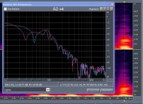
First, I assume from the various comments most of you folks are using some flavor of dB meter that yields an overall value based on one of the frequency summation scales, but that doesn't yield any sort of spectral results. For instance, your instruments won't necessarily tell you if the dominant noise is at, oh, 3450 or 6900 Hz, or some other value. This is not meant as a criticism, I'm just trying to understand what you're using, and what the results you're getting are telling us.

And here's why: 'Tis true enough blade passage is likely a huge generator of noise. The motor turns at 3450 RPM, and there are 6 blades to the compressor. So you could get multiples of 3450, and distinct spikes at those values, up to 20700 Hz, above human hearing (and well above mine). That will certainly tell you if it is blade passage of a single "feature" or obstruction.

However, if you're getting peaks at different frequencies, then the noise isn't necessarily due to blade passage at a single point. It may be, for example, the interaction between the two lips of the MDF in the transition, not "just" the passage of each blade past the PETG diverter (the sharp angled bit).

So my second question is whether or not anyone has attempted to modify or eliminate the transition's MDF protrusion into the PETG's "channel"?

What leads me to this is thinking about the air as its flowing out of each blade of the blower, and it crashing not only into the diverter, but also the sharp corners of the transition MDF.

If I'm correct, then it should be little trouble to modify the square edge of the transition's lip with, oh, a 45 deg. angle to smooth the transition, then maybe put a chunk of some sort of acoustic foam onto a bit of the PTEG and up the bevel, keeping it away from the blower, of course.

So, if anyone's tried a different sort of outlet, one that doesn't have 3/4 material on the inside of the PTEG blower surround, and found it really didn't do much to the noise, then I think that would successfully debunk this theory.

Anyone?

Regards,

DWD
 
Tone Generator

Tone Generator

As a follow on, and if you want to "convert" frequencies to what you're hearing, Google "Tone Generator" and up towards the top should be an outfit called NCH. They offer a trial version of their generator, which I just tonight downloaded and installed. You'll need some sort of sound capability on your PC, either built onto the motherboard (eg, Realtek) or a dedicated board (eg, SoundBlaster) and some halfway decent speakers or headphones.

You can also test your hearing while your at it. I knew mine was not all that good in the upper frequencies. Still OK around 10K, maybe a tad at 13K, but nothing above that except the constant ringing in my ears. I'd love to blame it on sex, drugs and Rock & Roll, but more likely it was destroyed by Garrett APUs. Muffs and plugs still aren't enough around those.

I know my speakers were working at those frequencies because the cat was going bonkers.

Regards.

DWD
 
dwdrury, I -think- I understand where you are going with determining the frequencies. I tried to figure out what they were prior to sound proofing, so I could tailor the materials I used. I downloaded a free frequency analyzer program for my laptop, but due to my own fault or whatever, I wasn't able to isolate anything useful. The frequencies seemed to be all over the place.

So, long story short, I just decided to use a basic meter to record the baseline loudness and any decreases associated with whatever modification I added. This way I knew if it was even a small improvement.

Earlier in this thread I was flip-flopping on what I was going to do with the alcove. Well, I decided to just enclose the top, and add an access door. I'm almost complete, and will post the pictures and results when I'm through.

I sure hope it's worth it.
 
Nipping it at the source

Nipping it at the source

Thanks for the reply, Woodman. And, yes, I think you've got a handle on where I'm going with this.

From what's been written here previously, it sounds (no pun intended) as though you were searching for an appropriate material with which to surround the blower housing, as a sort of sheet goods thing or wrap. Much like Nako's enclosure. And it certainly would have helped your material selection if you knew the tones you were trying to quash. For instance, things like Dynomat are supposed to be good for low frequency rumbles, I believe, whilst some of the acoustic foams I've seen are good for, oh, 5000 Hz and higher. Some I've seen in my limited look around the web are claimed to be good from 1000 Hz and up.

What I'm thinking about is trying to do more right at the source, right where the blades pass the blower outlet, much as is done in turbine engines where there's often a ring of material to absorb the overpressures associated with blade passage. That and smoothing the transition attachment area for less turbulence generation.

So far, and I'm not very far along with my search, I've found some fairly rigid melamine foam, open cell, which should withstand the environment. But I haven't found its tonal absorption parameters yet. I've also found some urethane foams, and a layered product meant to be installed inside computer cases to quiet them down. I have no idea if the urethanes or this two layer product will stand up to the airflow, and both are a tad on the pricy side to be doing a lot of experimenting.

It could very well be the trouble you experienced trying to isolate the tones was because there are several causes, even in that blower exit area. For example, and I'm just speculating, it could be that you get one strong tone due to the blade passing the diverter, then another from the MDF lip on the diverter side, then another on the other, outside. And you could get both airflow and sound wave interaction between the three, effectively muddying up the noise signature, as they're sure to be out of phase with each other.

But I do appreciate both your effort and your results, even if they weren't exactly what either you or I were looking for. It is another data point, something to be considered.

I'm sure there'll be more on this subject as I once again go overboard with the over-analysis. Good, bad, or just a waste of time and money, I'm sure it'll be useful for someone, so they'll at least know something NOT to try. Sometimes, knowing what not to do is also helpful.

Regards,

DWD
 
I'm sure there'll be more on this subject as I once again go overboard with the over-analysis. Good, bad, or just a waste of time and money,...

DWD

That's funny, because it's just how I feel....but I keep telling myself that even if it's not a complete success, I will have at least learned something from it...AND...the most important thing of all, regardless of noise, is that I'll still be collecting all the dust better then anyone around...except other clearvue owners, that is.

Back to the topic...I like where you're going with addressing the possible root cause of the noise, but that sort of engineering is beyond my skill set and available time. I figure, if I just enclose the thing and block all the noise, I'll be happy.
 
Maybe a cheap fix?

Maybe a cheap fix?

Might be beyond mine as well, Woodman. My specialty was thermo, not noise. And I'm very rusty at that, having been out of the game for almost 10 years. Unfortunately, most of the noise experts I could turn to have also retired and gone their separate ways. Probably a job hazard, but the ones I knew also sported hearing aids last I saw them.

I may have stumbled on a cheap way to test my little theory. In my wandering around on Google, with the search being "acoustic foam", it seems melamine foam yields a reasonably rigid structure that has a decent chance of surviving the environment. Tonight I found a few acoustic charts of the material's performance. Seems its absorption capacity works best between 1000 and 4000 Hz, then appears to start rolling off above that.

But if I'm right, then all I really need is to squash the blade passage tone at 3450 Hz, so this stuff should be fine. Also, as that tone is sort of midrange, without looking I'd also hazard its weighting in the dBA scale is also high. Don't quote me on that, though.

The Mr. Clean Magic Eraser is made from BASF's Basotect brand of melamine foam, and another Google source suggests one can obtain a pair of them for around $2 at various big box stores and supermarkets. Hmmm. I'm thinking we have a winner!

So here's what I think I'll be doing when I assemble my CV 1800: Think I'm going to bevel the ends of the transition sides. Maybe not all the way down the 3/4 thickness. Maybe just a deep chamfer, like 3/8 or so, to give a lip for the melamine block to rest against. Then I'll obtain a few of these blocks, cut them to shape, and probably profile one edge to match the MDF. The other is open to discussion. Then glue or double sided stickum tape them in place. At this point, I see no advantage to covering the melamine with another foam product.

The trick is going to be how close to get the blocks to the impeller, and whether or not to contour that edge.

I'm under no illusion this will make the beast whisper quiet. I think that's probably beyond the realm of possibility with just this simple mod. Your and Nako's solutions are likely to be most effective, but that's not an option for me.

It is unlikely I'll get to assembling and installing my CV until at least September, given the projects at hand and the promises I've foolishly made.

I'm also not sure whether melamine pieces stuck to the top and bottom of the blower housing's MDF, maybe some half rounds or the like, would have any effect or would just result in blockage.

One other cheap option occurs to me. Several of the products sold for this purpose are urethane foams, though their performance seems to be in the higher registers. Wait! Isn't Great Stuff urethane foam? Build a form, spray it in, let it foam.... Would probably have to cut off the skin it forms, though. And it probably won't be all that durable, subject to flaking off and gunking up the filters.

BTW, did find a couple of very nice hand held analyzers with spectral capabilities. Only problem is they're $300 and $400. Tough to justify for a one off, playing in the sandbox investigation.

But speaking of which, I don't have any of those SPL meters you folks seem to be using. Care to provide any details of brand, cost, sources? I won't be able to test the effect of the bevel by itself, as that'll have to be accomplished prior to assembling the transition, but unless bucks are prohibitive, no reason I couldn't do a before and after with the foam.

Regards,

DWD
 
Frequency measurement

Frequency measurement

DW,

Also being an amateur radio operator in addition to woodworking, I have a potential measurement idea for you (and others who want to try it).

We frequently use Soundcard software with FFT algorithms for measuring our input audio signals in either the time or frequency domains. Since hams are such a bunch of cheapskates, there is a plethora of free software available on the internet.

One I would suggest is GSpec v2.0 available at http://www.mrx.com.au/d_spect.htm. By downloading and installing this software to a PC or laptop equipped with a soundcard, and inputting an audio source from a reasonable good, flat response mic, you should be able to look at the source signal in the frequency domain. I have a hunch that a mic signal will be a mish-mash of stuff, very wide, so another thought would be to use one of those suction cup telephone handset pickup mics and stick it right on the PETG blower housing near the outlet to see if you can isolate the primary frequencies within the blower housing.

I would try it myself, but at the moment, I have nothing to measure :(

Will be watching this thread with some interest!

EDIT TO ADD: If I am calculating this properly, the fundamental pressure wave frequency coming from the blower housing should be about 345 hertz. (3450 rpm x 6 vanes = 20,700 vane passes per minute, /60 secs = 345 pulses per sec) It would take the 6th harmonic of this frequency to reach into the lowest register of human hearing, and with a fundamental at 345, the harmonics are quite close together, which would account for a very broad spectrum noise as previously described.

I am no sound engineer, all of this is based on applying radio frequency theory to sound pressure waves, and I am sure that there are significant differences. However, I would say that anything that can be done to reduce the amplitude of the fundamental source should go a long way to reducing the overall noise.

Best to all,
C.
 
Last edited:
Mea Culpa

Mea Culpa

Oops, that's two errors I made! Really getting rusty! Maybe three if you count getting out of bed this morning.

I neglected to turn the blade passage from minutes to seconds, thanks for pointing that out, Chris. Doh! That was really dumb of me!

The other I noticed last night when I went again to review some of the photos, notably yours, Woodman. Thanks for the great documentation. My error was the misconception the transition MDF side pieces went inside the blower housing's PETG when in reality they goes outside. Thus the only real possible source for blade passage noise, aside from the air just leaving each blade and bouncing around the PTEG, would be the interaction with the sharp angle at the diverter.

There may be a way to "fix" that one, too. I noticed while wandering around the web that various blower housings don't have that sort of sharp corner on the small side of the scroll. Instead they have almost a triangle shape there. I'm fairly sure those designs were so the upper and lower halves of the housing bodies could be stamped from single sheets, but I also wonder if the less radical transition also yields less noise due to a reduction in turbulence. Though such a transition would also probably negatively impact performance.

My old Delta blower has a similar radius in that area, and even with the thing in a corner of my shop, the noise from the machine is not objectionable. Now, is that due to the design in that specific place or due to other factors like impeller design? Don't know as yet and will have to do some more investigating.

I schemed out a way to do it, and there seems to be sufficient MDF in the supplied top and bottom blower housing pieces. One could rout a second channel in that area, with the radius of about the same as a 1 lb coffee can. Then make another PETG piece without the sharp bend but with the more gradual bend. I have time to roll this idea around some more as I probably won't be getting around to assembling my cyclone until September.

I did acquire some of those Mr. Clean Magic Erasers at a big box today. I figure that even if I can't use them for this application, maybe the wife can scrub something with them (and the going rate for your not mentioning to her I said this is $20). The blocks are an inch thick, about right for what I envisioned, but a bit short to cover the PETG, and stacking two, rotated the other way, is also a bit short. Need about 5.5", the blocks are 4.6" x 2.4" x 1". Which means to use them, there'll have to be some glue seams. Not ideal, but the price was right: 4 for less than $4.

I'll check out the frequency programs, Chris. Thanks for the pointers. Will also need some sort of microphone as the only one I think I have hidden away someplace is one of those old, cheap ones they used to give away with "multimedia" packages for old '486 computers, probably barely adequate for voice. Still have that expensive doorstop someplace around here, too. And might be able to get some more use out of it, assuming I can still get it to boot, by using it to snag a WAV file instead of trying to lug the current machine out to the shop. And if it won't boot, well then I have yet another "dust collector".

Regards,

DWD
 
Spectrum Analyzer

Spectrum Analyzer

Chris, d/l the trial version of GSpec. Cool! Did notice it is good for Win95 and sub, so that old 486 box won't do. The almost as old P-II box will, though. Now to try to find that old mike and see what sort of spectrum it will pick up.

Nako and/or Steve (Woodman): In my wandering, I, too, came upon the Acoustical Surfaces site. Was wondering if anyone's got any opinions on either their Duct V-Max or V-Blok VB-2 sheets, or called them to discuss? Was thinking if noise is caused by interaction between blade passages and the PTEG, might it not be a decent idea to line the PTEG with one of these products, on the inside? Stuff's thin enough so it shouldn't interfere with the blower.

Of course that also means the nice clear view of the blower in operation becomes somewhat problematic unless you're Superman, defeating part of the reason for using PTEG in the first place.

They're not quoting any prices on their site, that I've found yet. Suppose I can drop a dime if no one else has.

Regards,

DWD
 
Hi everyone.....I just wanted to chime in and say this is a great thread. Noise from these blowers has been an issue with us since we started. Personally, I haven't made much progress with trying to nip it at the source....so to speak. We have done some experimenting and the only positive result that I can report was inserting a cone over the center of the impeller which started at a point and extended out to the beginning of the blades. It was explained to me that this cone would keep the air from impacting on the impeller back plate....and, it actually did reduce the noise noticeably. Other than that, we have tried coating the inside of the blower housing with undercoating/sound proofing material and also coating the impeller itself. Neither of those made any difference in the noise level of the blower. No doubt there are materials out there that if applied in the right places and in the right amounts, would reduce the db level. The trick is to figure out what, where and how much.
Now, to the other approach. We just finished with our new shop and we installed a Max system. We built a closet inside the shop using 2x4 construction. I installed pink insulation in all the walls with the pink side facing to the inside. I lined the inside of the walls with window screen to contain the insulation and we used OSB board on the ouside of the closet. At 10' away, I measured 65 db with all the gates closed. I would love for you guys to come up with a blower setup that quiet. It would save having to build an enclosure. Keep this thread going.....

Ed
 
Noise Experimentation

Noise Experimentation

Ed,

If I understand what you're saying, then the noise is being generated where the air comes up the central tube and impacts the blower, not at the outlet end of the blower blades. That about right, per your experiment with the cone?

You wouldn't happen to have a photo of your experimental piece, would you? Stationary (attached to the housing bottom MDF panel) or glued onto the rotating impeller? And did it negatively impact throughput?

Also, can you tell me what sort of material soundproofing / undercoating material you applied to the blower surround?

Yes, the surround is the proven and probably best solution. But I don't think I have that option, and I'm pigheaded enough to see if there's anything else I can do. Apologies for the 3rd degree.

Regards,

DWD
 
Was wondering if anyone's got any opinions on either their Duct V-Max or V-Blok VB-2 sheets, or called them to discuss?

DWD, I don't have any knowledge of those products...but if it's anything like Dynamat, then I personally wouldn't expect a big improvement. After I applied Dynamat to mine, I wasn't that impressed. If it made any improvement, it was to a frequency I couldn't hear anyway. I think that stuff does better when applied to thinner substrates, like sheet metal which -could- propagate vibrations better then PTEG (i think). And once you put it on, forget about getting it off.

I finished the enclosure (I'll post pictures this weekend). And I gotta admit, with all the work and $$ spent, I wasn't impressed. I'm down to 83 DBA, which -is- an improvement over 98 when I started. I guess I had this unrealistic notion that the noise reduction would be commensurate with the amount of effort I put into it. HA! What a fool was.

I think the cone that extends below the bottom wall, and any noise that isn't suppressed by the muffler is circumventing any sound proofing I've done around the top. I also feel vibration on the floor, so hopefully I can improve isolation somehow. Anyone reading this is probably thinking, " Just enclose the whole thing!" ...I hear ya....and in the end, I just may put a removable panel at the bottom. I was hoping to avoid it though. It'll be just one more thing to move around an already cramped space.

The sound meter I use is Radio Shack model 33-2055.

I'm sure I'll have more to report later, I haven't given up.

p.s. Sorry I don't have any input on the science behind stopping the noise at its source. That's really not my specialty.
 
DWD,
This is an important topic so no problem with the questions. If we can make an improvement in the sound level it will be to everyone's benefit. I used Dynatron brand Dyna-Pro Paintable Rubberized undercoating & sealer to coat the entire blower housing inside and out and the impeller. It didn't help to any measurable degree. I don't have a picture of the cone, but I will try to make a drawing and attach it to this post. It was crude, but it worked. We took a piece of our PETG (you could also use Lexan) and put it over an piece of MDF with a 5" cutout in it. I used an 8" round piece of plastic. Then I took a propane torch and heated the center of the plastic till it got soft and carefully pushed a broom stick down through the center of the plastic to push out a cone. It was far from perfect, but it was a light weight cone. On the 15" impeller, there is about a 4 3/4" circle in the middle where there aren't any blades. I took my very crude cone and layed it over the blades and marked the location of the blades. I then cut slots in the plastic cone to match the blade. This cone then slipped right into the center of the impeller and actually wedged in. That's all we did. We tested this in a horizontal setup so the cone wasn't falling out the bottom and just the friction fit held it in place without a problem for our "sound test" which only lasted for about 60 seconds. The cone wasn't centered exactly (probably had a 1/4" wobble at the point of the cone) but it worked fine for reducing noise. I'll send the picture later.

Ed
 
Cones, Dynamat and Sound Meter

Cones, Dynamat and Sound Meter

Steve and Ed, thanks for the feedback.

First the Dynamat. I finally went to their site tonight, Steve, and from what I could gather, the Dynamat Xtreme you used is very similar to the other company's products, butyl rubber backed with a thin aluminum foil, meant to be stuck onto an offending panel. Just to be clear, though, you stuck yours on the outside, or both sides of the PTEG?

I also reviewed earlier posts, for my memory isn't what it used to be. I thought you said the Dynamat actually helped. though I might be confusing what you noted as a vibration dampening effect for actual noise reduction.

Noise is one of those "dimishing returns" sort of problems. I recall our guys fighting for a half a dB of flyover noise, and spending really big bucks to get it. As I recall, and the numbers probably aren't quite right, but going from, oh, 105 dB to 99.5 wasn't all that tough. But with the prize being able to get under 99, getting that last half a dB was a nightmare.

Rolling the idea around in my otherwise empty head last night, Ed, I thought of that, a cone attached to the center, nearly flat area of the impeller. Then I wondered, as almost certainly I wouldn't be able to dynamically balance it, how loud a bang it would make when it let go.

I was also thinking, which I admit is dangerous, that if the idea is to give the air a head start on turning, why some sort of deflector couldn't be attached to the lower portion of the housing, with some clearance to both the impeller plate and blades. Maybe via some sort of cross brace inserted into the center cylinder (where have we seen that idea before?).

It is enlightening, though, that it is possible the main generator of noise isn't the blade exit, but the blade entry. I hadn't considered that, more or less assuming it was due to the blades passing the exhaust port, specifically, the sharper edged "low" side.

I'm also going to assume that as your test lasted but a minute, no flow measurements were obtained. I'm guessing you, too, were concerned it might fly off and end up getting munched by the impeller.

The other idea I was rolling around for the cone was to use what they call "dock foam" around here, basically 4" thick sheets of a fine grain styrofoam-like material. We used to make various aerodynamic shapes with the stuff and stick 'em on the planes. If we lost one, and we would from time to time, no big deal as they had no mass to speak of and would usually land harmlessly in some farmer's field or the swamp. The impeller should be able to chew it up with no problem should it come loose.

Its probably best for me to quit speculating and get on with assembling my CV 1800. Then I can test all sorts of these ideas. The CV 06 installation is complete, and I'll be putting the photos in the gallery "d'reckly", as the locals say. 30 years down here and I still haven't been able to calibrate "d'reckly". Could be this afternoon, could be a month of Sundays from now. Ya never know.

I'll check out that Radio Shack meter, too. Thanks, Steve.

Regards,

DWD
 
DWD, I stuck the Dynamat only around the outside.

Yea, after reading that again, I wasn't very clear. One thing I can confirm, though, was that the vibration felt by my hand on the PTEG was much less after adding the dynamat. I can only assume this, along with adding the isolation mounts, contributed to the lower reading.

So, to date, here's how I remember the readings:

Open cyclone, no filters or muffler = 98
Open cyclone, filters and muffler = 94
Open cyclone, filters, muffler, dynamat and isolation mounts = 88
Open cyclone, filters, muffler, dynamat and isolation mounts WITHIN the enclosure = 83

I was thinking the same thing about that cone letting loose in the blower. That'd be quite a surprise!
 
Dynamat

Dynamat

Oh, I dunno, Steve. You got 6 dB out of the combo of isolators and Dynamat. That's not nothing!

Regards,

DWD
 
That is totally different than trying to reduce noise, though. Dynamat, and it's siblings, at least in the car audio world, is used more for dampening out vibrations that can affect the music reproduction. It takes the vibration and turns it into heat so it dissipates. Vibration usually from metal body panels.
I suspect that it helped some here, but not a lot. I bet most of your reduction came from isolating the cyclone, and the muffler. If you build a closet around the unit, build a folded horn or baffle style air return to the shop. Having the air change directions in the form of a squared "S" will cancel some of the sound. Same principal as a car muffler. (The louder types, such as glass packs, are straight flow types.) What happens is that the sound waves have to change directions and bump into themselves and partially cancel themselves out. A low tech version of the electronic noise canceling units, if you will. But I wouldn't do this to the cyclone muffler, as it also adds resistance. Make sure you have double or more square inch of vent area from the closet to the shop as you have output from the cyclone. I'd shoot for triple or more personally so it will slow the air speed coming out of the closet, and help with any noises created by the air moving. This would mean multiple baffles or wide ones. I'd try to keep the height of the slot around 4" or less, but make the runs 12" long or so. When I was thinking of using filters and returning the air to the shop, I was going to build mine in the attic, instead of the closet walls, so that the space taken for the baffle was not usable space. The electronic noise canceling devices take a sample of the sound, then reproduces it out of phase to try to kill that sound. With filters, you can isolate the frequency of the target noise, but keep other frequencies intact, so that while killing off offending noise, you can keep speech audible. This works best with low frequency sounds. To test it with your stereo system, select a song with a heavy bass beat to it. Take one speaker and reverse the leads, thus putting that speaker out of phase. You will lose a lot of the bass reproduction. If you gain bass, your speakers were out of phase to start with!
Hope this makes some sense! Jim.
 
noise

noise

i read this thread with great interest. My original background is industrial hygiene and sound measurement/abatement was part of my previous life. I am also a home theater enthusiast.

noise is a nasty thing. it is logarithmic. a 3 db increase in sound pressure is equal to TWICE the sound energy experienced by the ear. if you have brought the noise level down 6 db you now have 1/4 that of what you started...that is very good. as previously mentioned, the law of diminishing returns is likely to come into play hear. chance are good that hearing protection will always be required when using these, especially when combined with jointers, planers, table saws, etc.

The sound pressures you will be experiencing are going to be from air turbulence. chances are the impeller used in this cyclone perform great for our uses as dust collectors, but are not optimized for sound....it can be done, but at a cost...and there can be trade-offs. other "sources" of noise will be from Not decoupling the cyclone from where is is mounted. i believe hanging spring/neoprene mounts will be best. the noise from the cyclone being coupled will be low frequency, basically turning your wall (if it is mounted there) into a drum. i once mounted a compressor on my garage wall and it was capable of rattling the neighbors kitchen dishes (their kitchen was was about 15-18 feet from my garage wall).

low frequency sound is more difficult to abate since it travels through solid materials (better and faster than through air). so if you are trying to lower the noise of your cyclone and you haven't got a suspension system that decouples it from the wall/ceiling....redo that and you'll be ahead of the game. decoupling the ductwork might also be worthwhile depending how much vibration/noise transmission is due to that route. 6 or 8" of the appropriate diameter flex hose should do the trick. place it 8-10 duct diameters away from the cyclone inlet since you want the air "smooth" when entering the cyclone for best separation (aka listen to bill p.) when your best efforts to decouple are complete mass is the next strategy to reduce unwanted low frequencies. this can get unpractical, so i would leave it for now and next look at placement.

here's an experiment for you (if you have a subwoofer). this method is used to find the optimal subwoofer (though not necessarily the most practical) location for a subwoofer in a home theater. place the subwoofer in your seating position and use atest disc (avia, digital video essentials or your bass heavy music on an a-b loop). play whatever low frequency material you have and walk around the room listening for differences in quality and quantity of bass. As you find yourself in a corner, the sound pressure will increase significantly. lesson learned for your cyclone...corners are a bad spot from a noise stand point. the more adjacent walls, the more the bass will be reinforced. the measurements of your room will play a role in this as will the distance the cyclone is placed relative to each surface. you are best not to place some thing 2' from the ceiling, 2' one wall and 2' from the adjoining wall. if somewhere close to the middle of the room is possible, that is likely the "quietest" spot, though not likely the most practical.

high frequencies are easily reflected or absorbed by anything in their path. foams of varying densities and thicknesses are popular and effective. air sealing is important also. my personal pal of attack would be to put the whole cyclone in a sealed compartment. foam door sealing, door sweeps, caulking etc. if you enclose something, but leave 1% of a hole, you'll let a huge percentage of the noise out. as mentioned earlier, a baffle system with an insulation (similar to a muffler) should be added to the side of the closet to allow the air to re-enter the room. it should be 2-2.5 times the outlet size. you may also want to put the outlet close to the top so the exhausting airflow can remove heat from the motor.

if you want to take things a step further, an open or closed cell spray poly urethane foam kit like this http://foampower.com/store/two_component/index.html can be used in a 1" layer on the interior closet walls. it will absorb noise as well as seal. you could also spray a layer on the cyclone impeller housing....that would be an interesting before and after. A flexible seal would be required where the piping passes through the wall. an open cell low expansion foam or good old fiberglass would work.

hope this helps some of you out....hopefully i get to build my new shop and do all this to my own clear vue shortly!
 
Noise Perception and Meters

Noise Perception and Meters

And, Armstrr, the ear is a funny thing as it, too isn't linear. Three dB is half power, but it takes a 5 dB reduction for us to perceive a difference, and 10 dB for us to consider the reduction significant. Or so I've been reading.

Steve, I checked out the Radio Shack meter online, plus had a look at other online vendors, and it seems the Radio Shack unit is the least expensive while still capable of doing the job. Thanks for the pointer.

Regards,

DWD
 
Frequency components

Frequency components

I do not have a CV yet because I'm concerned with noise, so I would be happy to help ! Some posts mentionned it could be fun to identify noise frequency components ( 3560 Hz components ) , but I understood it was not yet done. If someone recorded the cyclone noise or if someone could record it, send me a .wav or .mp3 file of the cyclone noise and I will post back a similar frequency analysis to the one I include. I used a strange low frequency sound for this example.

The right part of the picture shows frequency (HZ) in vertical axis, time in horizontal axis and color indicates the level. The " whiter " the frequency components are, the higher the level is.

The left part shows frequencies and levels for right and left channels ( pink and blue lines ) where you see the dotted yellow line in the right part.

I really doubt that we will see clear 3560 Hz components, but it's worth analysing the noise ... just in case we could find something. For those who are interested, graphics come from Adobe Audition, a very good audio software I used to convert my old vinyls to CD.

Sorry for my bad english !
 

Attachments

  • Freq analysis.jpg
    Freq analysis.jpg
    91.3 KB · Views: 0
Back
Top