Wiring: Connecting the Motor

kinghong1970

New member
Sorry for so many questions...
i rarely touch anything over 12v... :D

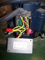
anyways, i am at the point where i am connecting the wire to the motors and i'm confused... motor once the panel was removed, looks like this... no labels, all the same yellow color and all so confusing to me... hahaha

_MG_2638.JPG


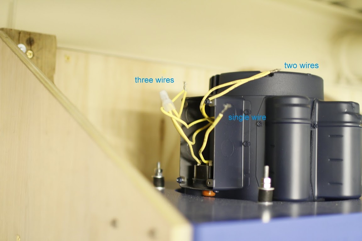
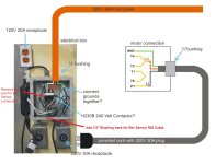
so i have 3 leads to connect... but have no clue how this translates to any of this:

_MG_2639.JPG


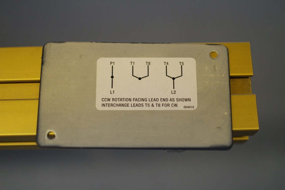
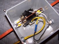
nor do i know where to connect it to:

_MG_2642.JPG


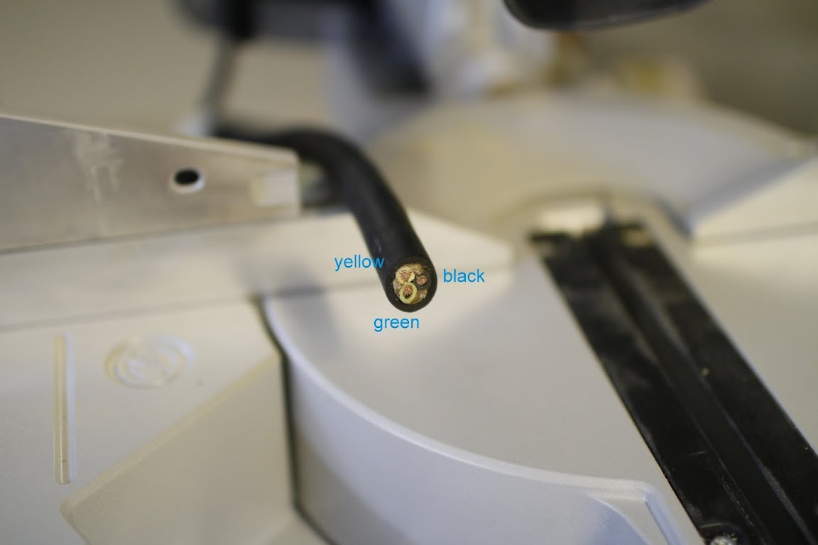
can someone teach me, as if you're teaching a 5 year old... yellow goes where, black goes where and green goes where?

i am getting an electrician to come and re-check my connections and mount/connect the electrical box...

thanks in advance,

Al
 
Al,
Inside the motor connection box you should see a green ground screw. The green wire on the cord should connect to it. Leads L1 and L2 on the connection diagram are the yellow and black wires of the cord. It matters not which way they go; they are interchangeable. If you look closely on the motor wires you should see them labelled P1, T1, T4, T5, and T8 on the insulation.
bababrown
 
Al,

I've attached a picture that shows my installation for the junction box on my Leeson motor on my CV1800. While you have a cord in your picture, I'm not certain how you are planning your end connections. For this application, you need an electrical box to house the H230B 240 Volt Contactor, bushings in that box to accept the 240 VAC feed from your electrical panel and to pass 240 VAC power to the junction box on the motor. I recommend using one of these six-foot "whip" conduit units from Lowe's or Home Depot, which have the appropriate gauge wire and ground wires and end connectors compatible with standard junction box knockouts and only cost about $10 and change. You will see the "el" connector and conduit entering the junction box in my picture at the top. If you do not buy a whip conduit, then you need a 1/2" bushing to secure your cord through the knockout on the top of the motor junction box. You need to remove about 6" of jacket from the cord to reveal the individual wires and strip each back about 1/2".

As Bababrown said, connect the green wire to the ground screw inside the junction box, being sure to capture all of the wire securely. Next, connect the Black wire to the single Yellow wire that is labeled P1 using a large Wire Connector nut. Your cord's Yellow wire (or the Red wire in the Lowe's whip) connects to a pair of Yellow wires that are connected and are labeled T4 and T5, also using a large Wire Nut. In your control box with the H230B contactor, add a bushing to secure the other end of your cord (or the whip conduit) and pass the wires into the box. Strip the cord jacket and wires as described above. Connect your Yellow and Black wires to one pair of the male connectors atop the H230B contactor; I recommend using Yellow female connectors like these (second from right in picture) for #10 wire. I've included a second picture that shows the use of these connectors on an H230B contactor inside a DC junction box -- the feed power from your panel goes to one side and the connection to your motor goes out the other side. The male connectors on each side of the H230B are for the 120VAC power to the coil of the contactor -- my photo shows the wiring for connection to the McRabbet Bin Sensor as well (the yellow cord brings in 120Volts from a remote outlet and the white jacketed NM cable at the right connects to the bin sensor -- one side of each is connected to the 120V coil connectors and a blue butt connector joins one wire from the 120Volt power to the lead out to the bin sensor).

Hope this helps.
 

Attachments

  • DC Control Closeup.jpg
    DC Control Closeup.jpg
    123.7 KB · Views: 1
  • 100_6947.jpg
    100_6947.jpg
    63.4 KB · Views: 1
Thank you Rob and Baba...

ok, so let me see if i got this straight.
here's an image i drew up to help me visualize the connections and to explain it better...

Fullscreen%2520capture%2520752012%252084505%2520PM.jpg


based on the above picture:

1) 220V 30A from my main panel to the electrical box (purchased from Clearvue) connecting L1 and L2 as labeled, and Ground together with the rest of the green?

2) Using the provided plug cord for 220V, i still need to make sure L1, L2 and Gnd from Electrical Box corresponds to the L1 and L2 and Gnd at the un-terminated end (to be connected to motor) right?

do i check this with continuity tester in multimeter or is there a color coded standard i can follow?

3) when i use the provided power cord with plug, i can bypass the recommended "whip"?

4) the H230B 240V Volt contactor, is this the thingy seen inside the electrical box? or something i need to purchase separately?

5) the terminated and pre-connected (longer) 110V power cord that comes out between the two receptacles on the electrical box, plugs into the power source and the short cord that comes out of the black plastic box (that is shown with the remote attached) plugs into the receptacle as shown, right?

sorry for so much noobie questions...
i guess the CV1800 is not quite a plug n play type of setup...

and not having much experience in wiring, this is a bit confusing...

oh, but i did find the fine print that is labeled on the yellow cords.

thanks again for all your help

regards,

Al
 
Al,
I'll respond in the same order as your questions.
1)Yes. Make sure all the green and only green wires connect to the equipment ground (the metal). Also, the two hot wires from the service panel connect to L1 and L2. If you use a white wire in the cable as a hot wire make sure you tape it with a black or red tape to identify it as a hot wire.
2) Correct.
3) Yes.
4) Yes it is the relay mounted in the box.
5) Yes.
One other thing that many are missing is a disconnect. Going back to at least the 2005 NEC a disconnect is required ahead of the controller (the relay) and the motor. The disconnect must be in sight from the controller, the motor, and the driven machinery. The locks that screw onto the breakers no longer are acceptable. If the service panel is not in view an AC disconnect (50 am) is an inexpensive way to meet the requirement. It adds only about $7.00 or $8..00 th the install.
bababrown
 
thank you very much for the reply Bababrown!

it helps a ton to take care of most of the work until the electrician gets here...

Al,
One other thing that many are missing is a disconnect. Going back to at least the 2005 NEC a disconnect is required ahead of the controller (the relay) and the motor. The disconnect must be in sight from the controller, the motor, and the driven machinery. The locks that screw onto the breakers no longer are acceptable. If the service panel is not in view an AC disconnect (50 am) is an inexpensive way to meet the requirement. It adds only about $7.00 or $8..00 th the install.
bababrown

ok i googled and learned that NEC you're referring to, is not the japanese electronics company... lol... learn something new every day...

so you're suggesting to place a disconnect on between the service panel and the electrical box (orange line)?

anything specific? or any recommendations?

thanks a ton

Al.
 
Al,
Yes. Home Depot sells a 50 amp AC non-fused disconnect that costs $7 or $8. It is rated at 10 HP (the 30 amp is rated less than 5 HP). Place it right near the Clear Vue electrical box and wire from the service panel to the disconnect to the clear vue box to the motor. The disconnect, clear vue box, and motor should all be in sight of each other.
bababrown

hmm... looking at home depot now...
by the way, why do they need to be in the same area? (just curious...)

thanks.
 
Al,
I think they are being very careful that people working on the controller or motor or machinery are not surprised by someone else turning the power back on. We used to be allowed to screw locks on the breaker handles but that is now gone and any locks now have to be individual, permanent devices.
bababrown
 
Al,

Looks like Bababrown has answered all of your questions -- I was unaware of you having the CV Electrical Bix when I suggested the "whip" -- he is correct that you do not need it since you have the cable with plug provided with your unit. One recommendation I would make is to use Yellow Female Quick Connectors for the L1 and L2 wire connections to the H230B.

Your picture is prefect to allow me to describe how to interface the Bin Sensor unit you also bought for your system. I've attached a marked up version of your picture to help with the Bin Sensor wiring connections.

You will find a spare knockout in the bottom of the electrical box (between the long power cord and 120 V Outlet bushings. You need to add a 1/2" bushing for NM (non-metallic) cable there and then run a piece of 14/2 NM cable to the Bin Sensor Box and make the connections to the T9A relay per my Installation Guidelines. Strip back about 6 inches of jacket on the other end of that cable, pass it through the new bushing and secure it in place.

Next, pull the Black wire that is connected to the left side of the H230B contactor coil with a female quick connector and cut the connector off the end. Using connectors I provided, connect this Black wire to the new Black wire in the NM cable. Put some black tape around the white insulation (use to mark the wire as being a hot wire per NEC) and add a new Blue Female Connector I provide to that wire. Attach it to the Coil male connector where you removed the Black wire and you've completed the Bin Sensor interconnection.

Hope this helps.
 

Attachments

  • Hong Contol Box Mods.jpg
    Hong Contol Box Mods.jpg
    122.9 KB · Views: 1
Last edited:
Ok so I had the electrician to come and check if wiring was fine..
All is well except one issue.

My home has 208V not 240...
Is this a problem or do I need to get a step up transformer?

Thanks again

Al
 
Al,
Huh! Excuse me but I've never heard of that in a home! Is it three phase, 120/208? Or is it 120/208, 3-wire single phase? I volunteer my time as gardener up the street at the Chinese Bible church. That building has 120/208, 3-phase only. There is no 120/240 single phase. Apparently, single phase is brought in as a separate service off a separate transformer. It is possible to run most single phase 230 volt motors off 208 volts and I know this motor has been tested that way. It's not ideal but the CV-1800 isn't loaded all that heavily. If you have single phase 208 volts I would call Motor Warehouse and ask them. Maybe give Clear Vue a call too. If you have three phase then I would back up and go with a three phase motor. I feel like Inspector Clouseau standing there without a sleeve on his jacket --- I should have asked you first if that is you're dog!
bababrown
 
Al,
Huh! Excuse me but I've never heard of that in a home! Is it three phase, 120/208? Or is it 120/208, 3-wire single phase? I volunteer my time as gardener up the street at the Chinese Bible church. That building has 120/208, 3-phase only. There is no 120/240 single phase. Apparently, single phase is brought in as a separate service off a separate transformer. It is possible to run most single phase 230 volt motors off 208 volts and I know this motor has been tested that way. It's not ideal but the CV-1800 isn't loaded all that heavily. If you have single phase 208 volts I would call Motor Warehouse and ask them. Maybe give Clear Vue a call too. If you have three phase then I would back up and go with a three phase motor. I feel like Inspector Clouseau standing there without a sleeve on his jacket --- I should have asked you first if that is you're dog!
bababrown

Bababrown...

i believe it is 120/208 3 phase that comes in to the home.
 
If it is 3-phase then go with the 3-phase CV-1800 motor. They are a better motor, they start better, and they run quieter and more efficiently. In a way I wish I had that problem.
bababrown
 
Albert,

If you have three-phase power, then I believe that the Orange wiring to your CV Electrical box will also need to be changed to accomodate the 3 phases. You'll also need to trade out the H230B contactor in that box with a Fasco H340B or a Packard C340B Contactor. These have the same 120V coil, but are 3-pole to switch the 3 legs of 208V/3 phase power. Best deal I could find in a simple Google search was the Packard C340B on Amazon.com.

The wiring for the interconnection with the McRabbet Bin Sensor is the same as I already recommended -- the Packard contactor has a 120V coil and that coil is connected the same way as the Fasco H230B. The difference is that there are three power feed that connect to the top side of the contactor. I would strongly recommend you have your electrician check the phases of wire and verify that you need a different feed to your electrical box. Like Bababrown, I am amazed that you have 208V/3-phase in your home!
 
thank you both...

so i have a "good" kind of a problem?

i guess i will have to contact clearvue to see about exchanging the motor to a 3phase motor.

i'll take a look at the links... it'll probably have to continue after i come back from vacation.

thanks again for the help.

Albert,

If you have three-phase power, then I believe that the Orange wiring to your CV Electrical box will also need to be changed to accomodate the 3 phases. You'll also need to trade out the H230B contactor in that box with a Fasco H340B or a Packard C340B Contactor. These have the same 120V coil, but are 3-pole to switch the 3 legs of 208V/3 phase power. Best deal I could find in a simple Google search was the Packard C340B on Amazon.com.

The wiring for the interconnection with the McRabbet Bin Sensor is the same as I already recommended -- the Packard contactor has a 120V coil and that coil is connected the same way as the Fasco H230B. The difference is that there are three power feed that connect to the top side of the contactor. I would strongly recommend you have your electrician check the phases of wire and verify that you need a different feed to your electrical box. Like Bababrown, I am amazed that you have 208V/3-phase in your home!
 
I could use some advice. I got started hooking up the motor wiring using info from this thread and especially kinghong1970's helpful illustration from 07-05-2012. All is clear except that there is another yellow wire labeled P3 that is not accounted for. P1 and P3 both connect to what looks like a capacitor in the motor connection box. I see that P1 connects to L1, but what does P3 connect to?

The motor came from the factory wired for clockwise rotation and P3 is wire-nutted together with two T1 wires. I can rewire for CCW rotation, but just need to know what to do with the P3 wire.

Thanks for any assistance.

Kim Kasdorf (Fingerpicker)
 
Fingerpicker,
You should have L1 connected to P1 and L2 connected to T4 and T8 where L1 and L2 are your two incoming wires. Then P3, T1, and T5 should be connected together. But they do not connect to any of the input wiring. The two capacitors are connected to the starter winding. That circuit can be wired two ways to determine the direction of rotation. That's why there is "extra" wiring in the box. You also should have the bare wire connected to the grounding screw in the box. The circuit diagram for the motor should be on the cover of the box. Hope this helps,
bababrown
 
Back
Top