Venting outside and ducting - I am brand new to dust collection

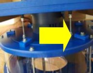
Blower Housing to Motor Plate Junction: Should it be caulked? I'm working on my own installation in parallel with Ed and now have a question for the group. I've gotten the blower housing loosely connected to the motor plate pending final adjustment (Step 7, Item 8). Should this joint between the blower housing and the motor plate be caulked? Nowhere in the instructions can I find any mention of this.

Picture is from Step 7, Item 8, in the Instructions...
Blower Housing to Motor Plate.JPG
 
Caulking the seam between the Blower Housing and Motor Plate is not necessary as it's a tight fit between the two. It won't hurt anything if you do seal between the two, but it does it make it more difficult to separate them if you ever need to disassemble your system.
 
Caulking the seam between the Blower Housing and Motor Plate is not necessary as it's a tight fit between the two. It won't hurt anything if you do seal between the two, but it does it make it more difficult to separate them if you ever need to disassemble your system.

Thank you, CVSupport, for the confirmation about this joint.
 
Thanks Rushton and CVSupport. This was a question I had queued. I have a couple others now.

For those of you who have taped inside your ductwork, or anyone who can answer...

1) My mains and planned drops have branches to go to my tools. They are on both sides of the main and some of the drops. In other words, some branches go left and some go right. When you tape inside, how do you deal with the branches? Does that question make sense? I don't know if I'm overthinking things or obsessing about perfect where perfect is not do-able. It almost seems to me like I have to have 2 strips of tape inside my ducts, one for each side of the pipe for continuity from end to end including the branches.

2) I believe I read that you lap the tape around the edge of the pipe before putting it in the joint. Given how tight I found these joints to be without tape, did I read that wrong, am I worrying about pushing the pipe too far into the fittings, or is there a trick to what I'm contemplating that I have not read? It seems like this would be a bit much to sand and I'm not sure lubrication would help.

3) If the tape is lapped, is this to have continuity with what is on the outside of the pipes, assuming that I do that? And if so, is the tape conductive on shiny and sticky side or is there another trick? Or is this addressed with the sheet metal screws I have read recommended?

I feel sometimes like I will never see done. I'm hoping to have the motor on the wall by next weekend. I am working the ducts first, so this tape question has some urgency.

Also, I saw foil tape in True Value yesterday but it does not explicitly say it is conductive. Is that necessary? Is foil tape implicitly conductive? I don't want to presume it just because it is shiny.

I got the rest of my elbows yesterday and 2 couplings just in case. My last filter arrived along with a sizable order from Rockler... all laying on my porch when I finished work. Like Christmas. I really hate that they do that though, given how some people are shopping people's porches. I live in the forest so it is less a concern, but I just wish they would not do that. The only thing I don't have yet is that dust collection barrel.
 
egbell,

I really doubt you are over-thinking anything. By my way of thinking and from my experience, installing duct work, especially when seeking to mitigate static charges, is an expensive and time-consuming undertaking. Ensuring that you understand exactly how you will meet the foreseeable challenges makes for a smooth installation that will work has it is designed and stand the test of time.

Foil Tape. Not all shiny silver tape is foil tape. If the package does not state the tape is aluminum foil tape, it may not be electrically conductive. I think it is prudent to test the tape for electrical conductivity. One method is to set volt/multi-meter probes at different spots on the shiny side of the tape. The meter, set to measure resistance, should read near zero resistance. A high reading indicts the tape’s surface is non-conductive. Since metal is generally expensive, a 50 yard roll of tape should cost over about $15. Tape that is non-electrically conductive would be unsuitable because non-conductive tape would not conduct static electrical charges to ground.

I have found that the adhesive side of the tape is non-conductive; only the metal foil side is conductive. Therefore simply sticking a piece of bridge tape to connect two separate strips of tape will not establish continuity between the two strips of separated tape. The methods of which I am familiar for establishing electrical continuity across two strips of otherwise separated foil tape are:

A piece of copper wire is placed in contact with each of the two separate strips of foil tape. The bare copper wire can be secured at each end with screws or it can be taped in place. I did not use copper wire. I used one of the two foil tape methods described below, depending on which method worked best for the circumstances.

A piece of foil tape is folded back onto itself where the crease of the fold runs the length of the tape, making the tape narrower without changing its length. About 1/3 of the width of the tape is folded onto a second third of the tape. This then leaves about 1/3 of the folded tape with a thin strip of exposed adhesive. This folding reduces the width of the tape while leaving its length unchanged. The exposed adhesive is used to temporarily attach the folded tape to the two strips of tape that are being electrically connected. A second unfolded strip of foil tape is the applied over the folded tape to permanently secure the folded tape in place.

The other method involves creating a tab that remains electrically and mechanically connected to the foil face of the tape and which is on the adhesive face of the tape. The tab is formed near the center of the tape (centered width-wise). Three cuts are made to create a three sided rectangle where the fourth un-cut end of the rectangle acts as a hinge for the tab. The tab is folded back onto the adhesive and the tab, now on the adhesive side of the tape, is placed over the strip of tape to which an electrical connection is desired. Since the tab is near the width-wise center of the tape, no further taping is required. If connecting two strips of separated tape, two tabs would be required.

Aligning foil strips. Duct work running in all different directions should not present a problem ensuring strips of adjoining foil tape meet and connect at the joints. In my installation (a single strip of tape inside and out lapped over the ends), the fittings and pipe were taped so that when installed the tape aligned.

I kept the foil strips of tape aligned by holding the fitting or pipe in position as it would be installed. The fitting or pipe was left unconnected since all that is needed if to locate the position of the foil tape on the next piece of duct work. I used a Sharpie to make a mark where the tape was to be applied. The tape was then placed over the mark and continued in a straight line. If the mark was well-placed and the just-taped duct work installed as it was aligned, the strips of foil tape should align. This method worked for me on the more complicated application of two strips of tape on opposite sides of the pipes and fittings. Therefore is should work with a single strip of tape.

If for some reason this method for aligning the adjoining section of tape cannot be used, then an electric bridge will have to be installed; as described above under “Foil Tape”.

Inside and outside foil taping. In my installation I applied foil tape inside and outside the pipe and fittings as a single piece of tape, lapping the tape over the ends. The first step was to cut a piece of tape that was 2Xs the length of the pipe plus about 1’ (plus about 6” for fittings). The paper backing was released from the tape as the tape was affixed to the pipe. I started and ended the tape on the outside of the pipe. I wiped the dust from the pipe or fitting to ensure a good bond of the tape and the pipe or fitting. The result was a single continuous strip of tape on both the inside and outside of the pipe lapped over the ends.

However, I did not have the issue you are facing. The pipe and fittings in my installation came together with firm hand pressure even with the tape wrapping around and in alignment with the adjoining taped fitting/pipe (without any lubricant like soap or water).

While the idea of using a screw to connect tape inside the pipe to the grounding circuit sounds good, I would be concerned that the screw may press against the tape on the inside of the pipe and not pierce the tape and thus fail to establish electrical continuity with the screw. If this method is used, then the screw should probably be installed and inspected to ensure the screw pierces the tape and then tested for electrical continuity between the screw head on the outside of the pipe with the tape inside the pipe using a continuity tester or a multi-meter before installing the pipe or fitting.

Before abandoning the idea of lapping the tape around the ends of the fittings and pipe, there is one more lubricant that might be worth a try. Perhaps coating the joint with a thin layer of graphite might make the fittings slip together. Graphite, as you may know, is a lock lubricate and very slippery. Graphite is also electrically conductive and available in many home centers and hardware stores. It can be found in a dry fine powder form or mixed with a solvent that evaporates. It is messy and makes every around it, including your hands, black.

I am not sure whether Teflon, also sold as a lock lubricant, is electrically conductive. If Teflon is electrically conductive, then it could also be used; otherwise I would be concerned that using Teflon could coat the aluminum and reduce its conductivity at the joint.

Aside. As an aside, the entire system for mitigating the PVC static charges should probably be tested to ensure each drop has continuity back to the cyclone. I found that testing each just-installed fitting or pipe for electrical continuity before proceeding to the next fitting worked well. Any problems were discovered when it was fairly easy to correct.
 
Jsbrow:

Wow! That was a great answer. I have read it twice already and I will need to read it some more to make sure I get it all, but you have answered some questions I did not even think to ask I never thought of making the strips inside and outside from a single run of tape. Never even occurred to me. Also, your comments indicate that the tape has a paper backing. I was not thinking that was the case either and started to worry about folding as you suggest being fraught with heartburn sticking on itself. That alone takes a lot of the dread out of the whole thing. I was thinking I'd have to wrap an end around a board, feed the board through the pipe, and stick it on like that. I'm trying to figure out how you did the branches off of a Wye... It may be in there and I have just not grasped it yet. Otherwise, I will need some more help with that. I went back through these posts because I could swear I saw a picture that might have helped me. I found one but it did not include Wyes. I'll keep poking around for an example of that.

The duct work has cost me about $400 so far. I think I have everything I need now... maybe just a bit more. The graphite... excellent suggestion that also would never have occurred to me. The guy with the video I mentioned about using screws also recommended the continuity test. My shop is a nightmare right now but I just want it to be right when I'm done so I'm moving slowly.

I was at Home Depot last night to exchange my switch and they do not stock (in store) the switches recommended here, and I picked up the tape but put it down when it did not explicitly say it was conductive. It did have a UL note on the packaging but I don't know if that is any guarantee of conductivity. I stopped in True Value yesterday and did the same thing with their tape. I don't know if 'foil' indicates conductivity or is a generic like 'duct tape'. (I just looked at your and Rushton's links and feel like a dolt. I had both types of roll IN MY HANDS and started second-guessing myself and put them back. I'll have my wife pick up a roll today. I think 50 yards will be enough. Definitely enough for the main runs. She has to go back over that way. The switch box I'm going to have to order online. One or more of you included links. I will use them and just order it.)

I made the duct adjustment I spoke of before... the one that rises from under the ceiling to inside it. I used 2 22.5 elbows. It will be a bigger cross section I have to cut in the ceiling panel when I put that all back together but it is going to work great and makes for a more gradual turn. That was the last difficult duct run thing I anticipated. I am going to turn my attention now to getting the motor mount installed so that I can get the cyclone in place and finish all of the main ductwork. I will be marking it all (ductwork) with a sharpie at the joints so that I can reassemble it all, pulling it all back out of the ceiling and taping it (which your post is really going to help), and putting it back up. I am drowning in 6 inch 45 degree elbows right now. I need to start getting things in final places!

Thank you! I am learning a LOT!
 
I have a question about the switch box recommended here... McRabbet provided a link for a switch box at Lowes (item #75 in this thread). I just looked and it is fusible.... I'm taking that to mean it requires fuses. Is that recommended? Necessary? I failed to read that the first time looked at the link. Home Depot does not have anything like this in their store and Lowes is even farther away and I don't know if they stock this either. I'll order online, but I want to understand this because this I have not seen discussed.... perhaps everyone reading this just understands this but I did not.
 
egbell,

Bear in mind I am not an electrician but when I have run new circuits, the county sent an electrical inspector by to check my work. I have had success with a 120v/270v 4 pole 30 amp switches like the one shown in the link below.

This style of toggle switch is in use on the three 30 amp, 240 volt circuits in my shop. I have seen no issues with these switches over the past 5 years. The electrical inspector made no mention of the switches during any of his shop inspections; either he overlooked or accepted the switches during the inspections, cannot say for sure. However if you are unsure whether this style of switch is acceptable in your installation, checking with the electrical inspector in your area would, I think, be prudent.

The toggle switches I used offer 4 poles where the pair of poles on the right side of the switch and the on the left side of the switch receive the two 120 volt legs of the 240 volt circuit. The bottom and top poles on both sides of the switch either establish or break continuity when the toggle position changes. There is no continuity between the right side poles and the left side poles. Before installing the switches I used a multi-meter set to measure resistance to ensure the switches behaved as I described.

https://www.homedepot.com/p/Leviton...BEgIbxvD_BwE&dclid=CPDByqONhdoCFQawTwodCvIPTw

A pull-out disconnect, like that installed near the central A/C compressions would also work as well as gray box lever action switches. I used the switch described herein above because they are small and convenient to use. But if you follow my lead, I recommend mounting the switch in a deep 2 gang box since the 10 gauge wires are difficult to bend and require a lot of room.
 
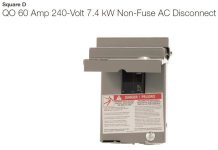
Ed, this is the disconnect I purchased from Home Depot for my electrical installation for $12.88. Its a 60 amp disconnect as would be used for an outdoor air conditioner unit. I bought this "Square D" brand unit because it has a toggle switch inside rather than the pull-out plugs (which I never feel comfortable using). If your Home Depot does not have it in stock, you can order it online for free delivery to the store. This is similar to the AC Disconnect McRabbet posted - neither has a breaker/fuse inside. They are a switch/disconnects only. I simply removed the closing front weather protection lid from mine so the face of the disconnect is exposed at all times.

Here is the link: Square D QO 60 Amp AC Disconnect

60A Disconnect.JPG
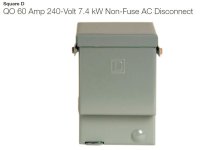
60A Disconnect - 2.JPG
(Note: this is the outside of the disconnect with the weather panel closed.)
 
Last edited:
Ed, one more thought on the AC disconnect... My electrician's opinion was that, since the motor was not hardwired, the receptacle and plug was itself a disconnect and no additional disconnect was required. He wired up my Clear Vue electrical switch box and power cord without touching the disconnect I'd purchased for him to connect. So, what you see in my post above actually became a "return" to Home Depot in my case.
 
Last edited:
Ed and others,

While I agree that using a CV Electrical Box with it's 240V plug on a whip that can be wired directly to the motor on the cyclone would "suffice" as a disconnect by some since the plug can be removed, it might not be acceptable to the local Code Inspector (the Authority Having Jurisdiction [AHJ] under NFPA or the NEC) as a valid disconnect. A disconnect switch (either fused or non-fused are mandatory for most serviceable 240 VAC equipment (like exterior HVAC heat pump compressors or a standalone air compressors) in most jurisdictions. The two shown by Rushton in Post #87 illustrate two non-fuse styles; one with a simple throw switch and a second that doesn't show its internals -- that style usually has a pull-out block that is simply reversed and plugged back in, showing ON or OFF in the top position -- these have heavy snap-in-place conductors that make (ON) or break (OFF) the two hot leads in the 240VAC feed. Another style may have a large throw switch arm on the right side and are available in fused or non-fused models. All of these have the advantage of being LOCKABLE which the cord approach does not have. When anyone is servicing this equipment, the NEC wants there to be a locking disconnect to protect the personnel that are performing the service. In the case of our cyclones, one could get at the equipment and forget to pull out the plug with potentially disastrous results. I strongly recommend a disconnect switch between the cyclone motor and the power feed, whether one has a CV Electrical Box or not.

Let me give another example -- we all turn off our table saws when we change a blade (e.g., putting a dado blade in), but do you also disconnect the power cord when you do it? Many people rely on the power switch as their disconnect and it is an invitation for disaster! I have a 3-wire Twist Lock plug behind my 3 HP cabinet saw and I ALWAYS pull that the plug out any time I make a blade change. My Grizzly saw has a switch that could potentially be tapped with my knee to start the saw -- the Stop button is right there too and is purposely placed so a knee can be used to stop the saw. For me, safety is paramount. For my cyclone, I have the equivalent of the CV Electrical box with a 240 VAC contactor and a wireless 120 VAC switch connected to the contactor coil inside a metal junction box for remote operations -- I have a 30 Amp disconnect before that junction box to disconnect all of the 240 VAC power feed in case I need to service the cyclone motor or blower. That puppy is not going to start accidentally while I am servicing it.

I know this a a bit of a soapbox, but I am a strong believer in safety and this is one place I will not cut corners for convenience to save $15. Sorry Rushton, but I don't support your electrician's opinion on this one!

One last point regarding fused versus non-fused disconnects. The fused versions are often equipped with Slo-Blo line fuses that duplicate the amperage of the main breaker on that circuit. They are there to protect the internal wiring between the breaker panel and the equipment and provide a second level of protection. I have had outside fused disconnects for Heat Pump units blow their fuses before the panel breaker of the same amperage tripped -- both were 60 Amp rated. The fuses should always match the breaker amperage rating (the AHJ should fail a 60 Amp disconnect on a 30 Amp breaker circuit). . Again, they are a safety feature.

Hope this helps -- IMHO, safety first.

Rob
 
Last edited:
Good safety discussion, Rob! Question: in my case, the breaker box for this circuit is 25 feet away in a direct line of view of the cyclone and electrical switch - does this make any difference to your cautions? I didn't mention this in my original post, but my electrician did talk about this as part of the reason he didn't see the need to insert the AC disconnect.
 
The hazard is not diminished by one's line-of-sight to the breaker. The disconnect should still be installed near the equipment.
 
Good morning:

These posts are a lot to think about. I had decided to forego the switch based on a much earlier post by Rushton about his electrician saying a switch requirement was satisfied by a plug. I’m having second thoughts now. I saw his point but I also see Rob’s point. I am one who also unplugs my table saw when changing blades. I have a healthy respect for the quick work a table saw could make of any part of me and the cost is not enough to really factor into my decision.

I believe I have to take responsibility for any decision I make, and I take all of your advice in that context. The same as if I were to jump off a bridge at the urging of any one here. The consequences would be on me. I know you are not electricians but I also know that having a degree does not necessarily make anyone smarter than anyone who does not. I’m leaning on you because you have done what I’m attempting. I respect all of your opinions knowing that my circumstance is unique. It makes for some difficulty processing the different recommendations though because I am reading all of the posts, current and way old, many also coming from you (plural). I’ve had to weigh 8 vs. 10 gauge wire, 30 vs. 60 amp breaker because of 5 horsepower motor, 30 vs. 60 amp switch, fusible or non-fusible, etc. I get where I need to be eventually but all the options have led to all the questions.

I had initially bought a box such as Rob described with the pull out tab with ON/OFF embossed. I returned it because I was not comfortable with that. Hands too close to the actual connectors. May be silly, but I am sometimes. That is where I started running into difficulty because there are so many different considerations. A lot of the points here come with gaps (for me) that I believe some of you fill with your own knowledge in presuming that others (I) have that same knowledge or grasp. I’m getting clearer. Here is my takeaway from your posts, and I’m not endorsing or disputing any approaches or opinions that are different:

1) I need to get a switch. You have provided many links and now clarity because some are switches, some are enclosed breakers, etc. etc. etc. I’m more clear now on what to get. (And as Rushton said, it is time to ‘move forward’)

2) The switch may or may not be fusible but, if it is, the fuse should match the amperage of the breaker in my main box, which was another point of confusion for me until now. This was a mistake in the making until Rob’s post.

3) Since I’m using 10 gauge wire, the breaker, already purchased, is 30 amp so I need a 30 amp rated switch
.

These three things may seem obvious, but to me they were not really. (and I don’t know if there are yet other “unknown unknowns” ahead)

I am going to try to get the mechanism in place today to get my motor assembly lifted. Once that is done I will work on getting the duct work mains connected. After that the wiring becomes the focus so I have time to get this stuff figured out. I am listening to everything said and sorting it all out. It is a snarl sometimes!

Thanks for continuing to add light because my situations in this whole journey get very confusing at times.
 
The hazard is not diminished by one's line-of-sight to the breaker. The disconnect should still be installed near the equipment.
I thought you might say this! Okay, I'll perhaps have to re-purchase and install that AC disconnect. I'll look at how involved doing this as a retrofit may be.

Since I’m using 10 gauge wire, the breaker, already purchased, is 30 amp so I need a 30 amp rated switch.
Ed, you should get the 60 Amp AC disconnect if non-fused because of the 5HP motor. This can be the standard outdoor AC disconnect for air conditioning units. The Square D model from Home Depot, to which I provided a link earlier, HAS A SWITCH rather than the pull out tab. I'm like you, those pull out tabs make me uncomfortable. The switch on it looks like a breaker, but it is only a switch and is not fused.
 
Rushton,
The disconnect must disconnect both the motor and the controller. So place it before the control box.
bababrown
 
Good afternoon:

I went to Lowes earlier today and got the switch in the link that some of you have provided.... 30 amp and I believe it is fused. Lowes is an hour drive but it is beautiful... most all of it right along the Allegheny River. If the 60 amp switch is not fused why is it called a 60 amp switch? I picked that very box up (the 60 amp one that looks like a breaker) and decided against it because of that breaker appearance. I suspect I have read the same things you have, Rushton, about the 5 HP motor and the initial draw, etc. Did I get something incorrect again, or sub-optimal? If so, I'll return it and get the 60 amp. This is where I get confused.

I saw something at Lowes that makes me think I have now seen everything. I got a 4x8 sheet of 3/4 plywood for the back board of my motor mount. I'm trying to video what I'm doing because this is kind of complicated to explain. I hope to have my motor up by next weekend at the very latest. Moving slowly, but moving. Anyway, some of the plywood is no longer 4 foot by 8 foot. It is now 3.98 foot by 7.98 foot, and some of them had the thickness in decimal too... the one I saw was just a bit lower than 5/8. I'm wondering how dumb we customers look. Or perhaps most people just don't read the labels. I had not even gotten used to the 15/32 kind of thing yet. I *thought* I had seen it all a couple weeks ago when I found a video of a guy with a stump attached to the drive wheel of a mini-van. He was holding a 4 or 5 foot length of steel pipe with a gouged the end on the spinning stump.... like a lathe. I found this while researching dust collection and cabinet modifications. This project has exposed me to a lot of wonderful things.
 
Did I get something incorrect again, or sub-optimal?

Ed, more knowledgeable heads than mine will have to chime in on this question. The research I did led me to the 60 amp non-fused AC disconnect. I don't know about the 30 amp switch. Sorry not to be of any help here.
 
On a 240 VAC circuit with a 30 AMP breaker, a fused disconnect rated at 30 AMPs must be used, but 30 AMP or 60 AMP rated non-fused disconnect switches could be used at the device. A switch is rated for the amperage it can handle and does not provide protection for the circuit wiring which the fused disconnect do provide. As for the pull-out block style non-fused disconnects, there is no opportunity for the user to be shocked since the connections are internal to the device and the exposed conductors on the block are not energized when they become exposed. They are very safe.
 
Back
Top